Table of Contents
What is Pipe Spacing and How to Use a Pipeline Spacing Chart
In my 20-plus years of piping engineering, I have seen minor layout oversights turn into multi-million dollar field modifications. One of the most common culprits is improper pipe spacing on multi-tier pipe racks. During my early days on a major refinery expansion project, a designer ran a hot steam line directly adjacent to a cold utility line using standard cold-spacing dimensions. When the plant went online, the thermal expansion caused the hot line to bow laterally, crushing the insulation of both lines and causing severe thermal bridging. This mistake taught me that pipe spacing is not just a drafting exercise; it is a critical safety and operational parameter.
To prevent these field clashes, we rely on a standardized pipeline spacing chart. This chart serves as our primary reference during the initial layout phase. However, as a professional engineer, you must understand the underlying physics, thermal dynamics, and mechanical constraints that govern these charts. We cannot simply copy numbers from a table without verifying the specific design conditions of our system.
Key Takeaways for Piping Designers
- Always account for the maximum outer diameter, including insulation thickness and flange ratings, not just the nominal pipe size.
- Stagger flanges on adjacent lines to optimize space and reduce the overall width of the pipe rack.
- Incorporate dynamic thermal expansion movements calculated via stress analysis software rather than relying solely on static charts.
- Maintain a minimum clear gap of 25 mm (1 inch) between the outermost projections of adjacent lines to allow for structural tolerances.
Why Proper Pipe Spacing Matters in Piping Design
When designing a piping layout, we must look at the system as a dynamic, moving entity. Pipes expand, contract, vibrate, and deflect under pressure and weight. If the pipe spacing is too tight, these movements will cause adjacent lines to clash, leading to mechanical wear, insulation damage, and eventual line failure.
The Fundamental Spacing Formula
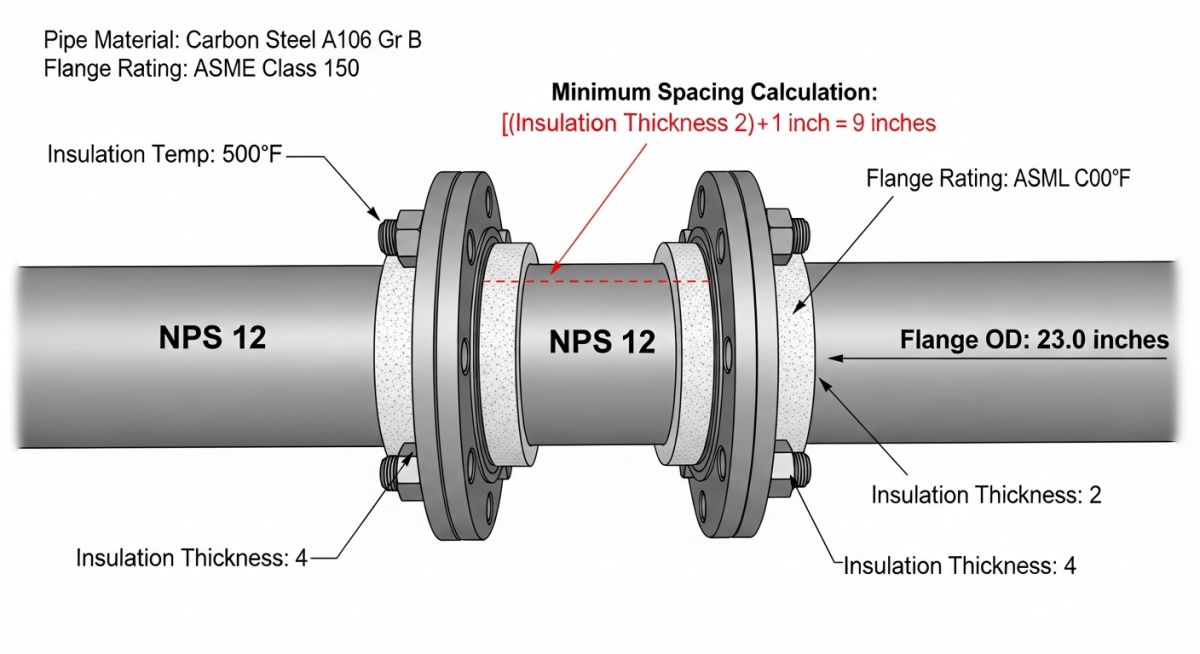
To calculate the minimum center-to-center distance between two parallel pipes, we use a basic geometric formula. This formula must be adjusted based on whether the lines are insulated, flanged, or subject to thermal movement.
Where:
- OD1 and OD2: The outside diameters of the adjacent pipes (or the outside diameter of the flanges if they are aligned).
- Clearance: The minimum required air gap, typically 25 mm to 50 mm, to allow for installation tolerances and painting access.
- Insulation1 and Insulation2: The radial thickness of the insulation on each respective pipe. If a pipe is bare, this value is zero.
Accounting for Flanges and Staggering
Flanges have a significantly larger diameter than the pipe itself. For example, a 6-inch Class 300 flange has an outer diameter of 318 mm, while the pipe itself has an OD of only 168.3 mm. If we align the flanges of two parallel pipes, the required spacing increases dramatically.
To optimize rack space, we stagger the flanges. This means the flange of Pipe 1 is positioned longitudinally away from the flange of Pipe 2. In this configuration, the spacing calculation is based on the flange OD of one pipe and the bare (or insulated) OD of the adjacent pipe. This simple design choice can reduce the required width of a pipe rack by up to 30 percent.
Thermal Expansion and Dynamic Movement
Static spacing charts assume the piping remains in its cold, installed position. In high-temperature systems, thermal expansion causes the pipe to grow in length. This longitudinal growth is often converted into lateral movement at elbows, expansion loops, and offsets.
We calculate thermal expansion using the formula: Expansion = Length * Coefficient * Delta T. If a hot line expands laterally by 50 mm, and the adjacent cold line is static, the cold spacing must be increased by at least 50 mm to prevent contact. I always recommend running a formal stress analysis in CAESAR II for any lines operating above 120 degrees Celsius to map these displacements accurately.
How to Read a Pipeline Spacing Chart Correctly
The table below provides the standard center-to-center spacing (in millimeters) for parallel pipes on a rack. These values are calculated based on carbon steel pipes conforming to ASME B36.10M, using Class 150 and Class 300 flanges with a standard 25 mm clear gap.
| NPS (Pipe 1) | NPS (Pipe 2) | Bare to Bare Spacing (mm) | Flange to Bare Spacing (mm) | Flange to Flange Spacing (mm) |
|---|---|---|---|---|
| 2″ (60.3 mm OD) | 2″ (60.3 mm OD) | 85 | 135 | 185 |
| 3″ (88.9 mm OD) | 3″ (88.9 mm OD) | 115 | 170 | 225 |
| 4″ (114.3 mm OD) | 4″ (114.3 mm OD) | 140 | 205 | 270 |
| 6″ (168.3 mm OD) | 6″ (168.3 mm OD) | 195 | 270 | 345 |
| 8″ (219.1 mm OD) | 8″ (219.1 mm OD) | 245 | 330 | 415 |
| 12″ (323.8 mm OD) | 12″ (323.8 mm OD) | 350 | 455 | 560 |
Note: The values above do not include insulation. If either line is insulated, you must add the full radial thickness of the insulation to the spacing values shown.
To ensure complete alignment across different engineering standards, this matrix maps the core technical entities, structural acronyms, and physical parameters used in spacing design.
| Entity / Parameter | Standard Reference | Engineering Purpose | Design Impact |
|---|---|---|---|
| NPS (Nominal Pipe Size) | ASME B36.10M | Defines the standardized size of the pipe. | Determines the baseline OD for spacing calculations. |
| Flange OD | ASME B16.5 | Defines the outer diameter of the flange connection. | Requires staggered layouts to prevent massive rack widths. |
| Thermal Expansion | ASME B31.3 | Calculates physical movement under operating temperatures. | Increases the required clearance to prevent dynamic clashes. |
| Insulation Thickness | ASTM C585 | Defines the radial thickness of thermal insulation. | Directly increases the physical outer diameter of the line. |
Field Verification of Pipe Spacing on Racks
Once the design leaves the 3D model, the field construction team must execute it with precision. However, site tolerances and structural deviations can compromise the designed clearances. I have developed this checklist over years of field audits to ensure that installed piping meets all safety and maintenance requirements before commissioning.
Construction & QA/QC Spacing Checklist
-
Verify Cold Clearance: Measure the actual physical gap between bare pipes or insulation jackets. Ensure it is at least 25 mm at the tightest point.
-
Check Flange Staggering: Confirm that flanges on adjacent lines are offset longitudinally as per the piping layout drawings.
-
Inspect Bolt-Withdrawal Clearance: Ensure there is sufficient space to remove flange bolts without striking adjacent pipes, structural steel, or instruments.
-
Assess Thermal Movement Paths: Identify high-temperature lines and verify that their predicted expansion paths (lateral and longitudinal) are completely clear of obstructions.
-
Validate Support Alignment: Check that pipe shoes and guides are centered on the structural steel to allow for thermal sliding without falling off the beam.
Field Case Study: Real-World Application
The Problem: Thermal Clashing on a Utility Rack
During a refinery expansion project in 2024, a 12-inch steam line operating at 350 degrees Celsius was run parallel to an 8-inch cooling water line on a multi-tier pipe rack. The design contractor used standard cold spacing from a generic chart without calculating the dynamic thermal expansion or accounting for the 100 mm calcium silicate insulation on the steam line. During commissioning, the steam line expanded laterally by 75 mm at an elbow offset. This expansion crushed the insulation against the cooling water line, causing severe thermal bridging, localized boiling in the cooling water, and structural overloading of the pipe rack guides.
The Outcome: Engineering Rectification
I was called to the site to troubleshoot the issue. We immediately modeled the system in CAESAR II to analyze the thermal stress and displacement. To resolve the clash without rerouting the entire rack, we shifted the cooling water line laterally by 150 mm on the support beams, replaced the crushed steam insulation with high-density aerogel insulation (which has a thinner profile), and installed directional guide supports to control the lateral thermal bowing. This restored the required 50 mm clear air gap, eliminated the thermal bridging, and saved the client from a potential plant shutdown.
This case highlights why we must treat pipeline spacing charts as preliminary guides rather than absolute laws. Dynamic stress analysis is always required for high-temperature or high-pressure systems.
Frequently Asked Engineering Questions
What is the standard minimum clearance between uninsulated pipes?
How do you calculate spacing when flanges are staggered?
Does ASME B31.3 specify exact pipe spacing dimensions?
How does insulation thickness affect the pipeline spacing chart?
What are the consequences of inadequate pipe spacing on a rack?
How do you handle spacing for pipes with different thermal expansion rates?
===
Complete Course on
Piping Engineering
Check Now
Key Features
- 125+ Hours Content
- 500+ Recorded Lectures
- 20+ Years Exp.
- Lifetime Access
Coverage
- Codes & Standards
- Layouts & Design
- Material Eng.
- Stress Analysis

📚 Recommended Resources: pipe spacing
Read these Guides
🎓 Advanced Training


Related posts:
![An engineer performing an API 579 fitness for service assessment on an industrial pressure vessel.]()
How to Perform API 579 Fitness for Service Assessment
![3D CAD render of a bolted flange joint assembly showing a compressed gasket.]()
Understanding Gasket m and y Factors in Flange Design
![PASS/START-PROF 4.86 pipe stress analysis software interface displaying a 3D piping model.]()
PASS/START-PROF 4.86 Released: Discover the New Pipe Stress Analysis Capabilities
![ASME certification mark stamped on an industrial pressure vessel nameplate]()
What is ASME Certification? Procedure and Mark Explained
![Professional technician inserting a high-pressure hydro jetting nozzle into a sewer pipe cleanout.]()
What is Hydro Jetting and How Does It Work?
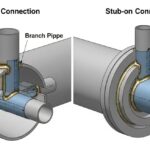
![Side-by-side comparison diagram of stub-in and stub-on piping branch connections.]()
Stub-in vs Stub-on Piping Connections: Engineering Design Guide