What is a Petroleum Tank? Types, Standards, and Design
In my 20-plus years of field experience in piping and terminal design, I have walked through dozens of tank farms, from coastal crude terminals to high-pressure refinery storage yards. I can tell you firsthand that a petroleum storage tank is far more than just a giant steel bucket. It is a highly engineered, dynamic system designed to manage volatile hydrocarbons under varying environmental conditions.
When we design these systems, we are balancing structural mechanics, fluid dynamics, and strict environmental regulations. A minor oversight in selecting the roof type or calculating the corrosion allowance can lead to catastrophic failures, massive product loss, or severe regulatory penalties. This guide draws on my decades of field engineering to break down the core mechanics, design standards, and practical realities of modern petroleum storage assets.
Key Engineering Takeaways
- Standard Compliance: Atmospheric tanks operating up to 2.5 PSI are governed by API Standard 650, while low-pressure vessels up to 15 PSI fall under API Standard 620.
- Vapor Management: Floating roofs are the primary defense against product evaporation, reducing volatile organic compound (VOC) emissions by up to 98 percent.
- Material Selection: Carbon steels like ASTM A36, A516, and A573 are selected based on design temperature, minimum design metal temperature (MDMT), and product corrosivity.
- Foundation Integrity: Concrete ring walls are the industry standard to prevent differential settlement, which is the leading cause of floating roof binding and shell buckling.
- Maintenance Protocols: Regular out-of-service inspections per API Standard 653 are mandatory to monitor floor plate corrosion and shell thinning.
Complete Course on
Piping Engineering
Check Now
Key Features
- 125+ Hours Content
- 500+ Recorded Lectures
- 20+ Years Exp.
- Lifetime Access
Coverage
- Codes & Standards
- Layouts & Design
- Material Eng.
- Stress Analysis
What is a Petroleum Tank and Its Types
To truly understand what is a petroleum tank, we must look at how we categorize them based on their structural design and the vapor pressure of the stored product. In my projects, selecting the wrong tank type is a costly mistake that can lead to excessive vapor loss or, worse, structural failure.
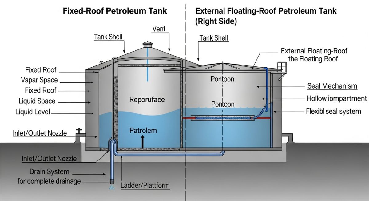
1. Fixed-Roof Tanks (FRTs)
These are the simplest and least expensive tanks to construct. They feature a permanent, welded roof that can be cone-shaped or dome-shaped. They are typically used for low-volatility products with high flash points, such as heavy fuel oil, diesel, lube oils, and asphalt.
The major drawback of a fixed-roof tank is the vapor space (ullage) above the liquid. As the tank is filled, vapors are pushed out into the atmosphere. As the tank is emptied, air is drawn in, creating a potentially flammable mixture. To mitigate this, we install conservation vents (pressure-vacuum valves) or nitrogen blanketing systems.
2. External Floating-Roof Tanks (EFRTs)
For highly volatile products like crude oil and motor gasoline, an external floating roof is the industry standard. The roof floats directly on the surface of the liquid, rising and falling with the product level. Because there is virtually no vapor space, evaporation losses are minimized.
The floating deck is equipped with a primary and secondary rim seal system to close the gap between the deck and the tank shell. However, because the roof is open to the elements, it must be designed with a roof drain system to prevent rainwater accumulation from sinking the deck.
3. Internal Floating-Roof Tanks (IFRTs)
An internal floating-roof tank combines the structural protection of a fixed roof with the vapor-saving benefits of a floating deck. The floating roof rides on the liquid inside, while a fixed cone or dome roof covers the top of the tank.
This design is highly favored in regions with heavy snowfall or torrential rains, as it eliminates the need for complex roof drain systems and protects the floating deck seals from wind and UV degradation.
Mechanical Design Calculations: Shell Thickness
The design of the cylindrical shell is based on hydrostatic pressure. Under API 650, the minimum shell thickness is calculated using the One-Foot Method, which calculates the design stress at a point 0.3 meters (1 foot) above the bottom of each shell course.
API 650 One-Foot Method Formula:
td = [4.9 * D * (H – 0.3) * G] / Sd + CA
tt = [4.9 * D * (H – 0.3)] / St
Where:
- td: Design shell thickness (millimeters)
- tt: Hydrostatic test shell thickness (millimeters)
- D: Nominal tank diameter (meters)
- H: Design liquid level (meters)
- G: Design specific gravity of the stored liquid
- Sd: Allowable stress for the design condition (Megapascals)
- St: Allowable stress for the hydrostatic test condition (Megapascals)
- CA: Corrosion allowance (millimeters)
In my practice, we always calculate both values for each shell course and select the larger of the two, rounding up to the nearest standard plate thickness. The bottom shell course is always the thickest, with thickness progressively decreasing for upper courses as hydrostatic pressure drops.
Standard Design Parameters for Petroleum Tanks
The table below outlines the critical design boundaries that separate atmospheric storage tanks from low-pressure vessels. Understanding these limits is essential when selecting the governing design code for your terminal project.
| Design Parameter | API 650 Limits | API 620 Limits | Typical Field Application |
|---|---|---|---|
| Internal Pressure | Up to 2.5 PSI (17.2 kPa) | Up to 15 PSI (103.4 kPa) | Atmospheric vs. Low-Pressure Storage |
| Design Temperature | -40°F to 500°F (-40°C to 260°C) | -325°F to 250°F (-198°C to 121°C) | Heated Fuel Oil vs. Cryogenic LNG |
| Joint Efficiency | 0.70 to 1.00 (Based on NDT) | 0.85 to 1.00 (Strict Radiography) | Determines weld inspection requirements |
| Bottom Design | Flat, lap-welded plates | Single or double curved bottoms | Hydrostatic support vs. pressure containment |
This matrix maps the primary structural components of a petroleum storage tank to their corresponding material specifications and design functions.
| Component | Common Material Grades | Governing Standard | Key Design Function |
|---|---|---|---|
| Shell Plates | ASTM A36, A516 Gr. 70, A573 Gr. 70 | API 650 Sec. 4 | Resists hydrostatic pressure of stored liquid |
| Annular Bottom Plates | ASTM A516 Gr. 70 (Normalized) | API 650 Sec. 5.5 | Transfers shell bending moments to foundation |
| Floating Roof Deck | ASTM A36, Carbon Steel (3/16″ min) | API 650 Annex C / H | Minimizes vapor space and product evaporation |
| Wind Girders | ASTM A36 Structural Shapes | API 650 Sec. 5.9 | Prevents shell buckling under wind loads |
Site Inspection Checklist for Petroleum Tanks
Before any hydrocarbon enters a newly constructed or repaired tank, a rigorous field verification must be performed. In my experience, skipping these checks can lead to immediate operational issues, such as floating roof hang-ups or foundation settlement.
Pre-Commissioning Field Checklist
-
Hydrostatic Test Validation: Verify the tank has been filled with water to the maximum design liquid level and held for at least 24 hours to check for leaks and monitor foundation settlement.
-
Weld Radiography Review: Confirm all butt welds in the shell have undergone radiographic testing (RT) per API 650 Section 8.1, and that all film records are signed off by a certified Level II technician.
-
Floating Roof Seal Clearance: Measure the rim space gap around the entire perimeter of the floating roof. Ensure the primary and secondary seals maintain continuous contact with the shell plate.
-
Vacuum Box Testing: Ensure all bottom lap welds have been vacuum box tested at a minimum of 5 PSI vacuum to verify zero leakage through the floor plates.
-
Grounding and Lightning Protection: Verify that copper grounding cables are securely bonded to the tank shell and connected to ground rods, with resistance measuring less than 25 ohms.
Field Case Study: Real-World Application
The Problem: Floating Roof Binding Due to Settlement
At a coastal crude terminal, a 150,000-barrel external floating-roof tank (140-foot diameter) began experiencing severe operational issues. During a routine pump-out, the floating roof hung up on the third shell course, causing a partial vacuum beneath the deck and risking a catastrophic roof collapse.
Our engineering team was called in to investigate. We performed a 3D laser scan of the tank shell and analyzed the foundation settlement data. We discovered that the concrete ring wall had settled unevenly by 4.5 inches on the southern quadrant, causing the tank shell to ovalize and pinch the floating roof.
The Solution: Precision Jacking and Foundation Remediation
We immediately took the tank out of service, cleaned it, and gas-freed the interior. To correct the shell ovality, we implemented a synchronized hydraulic jacking plan. We positioned 24 high-capacity hydraulic jacks around the settled quadrant of the tank shell.
The shell was slowly lifted back to its design elevation while monitoring stresses with strain gauges. Once leveled, we pressure-grouted the void beneath the bottom plates with a high-strength epoxy grout and repaired the concrete ring wall. We also replaced the damaged primary mechanical shoe seal with a modern double-wiper seal system.
Direct Engineering Recommendation
Based on this field experience, I highly recommend implementing annual settlement surveys for all tanks exceeding 100 feet in diameter, especially those built on soft coastal soils. Catching settlement early allows you to perform minor foundation shimming before the shell deforms enough to bind the floating roof.
What is a Petroleum Tank FAQ Guide
What is the primary difference between API 650 and API 620 tanks?
Why is a frangible roof joint critical for fixed-roof tanks?
How often must a petroleum tank undergo an API 653 inspection?
What is the purpose of a wind girder on an open-top tank?
How does a double-deck floating roof differ from a pontoon roof?
What is the role of an anode system in tank bottom protection?
===