Table of Contents
What is an Orifice Flowmeter and How Does It Work
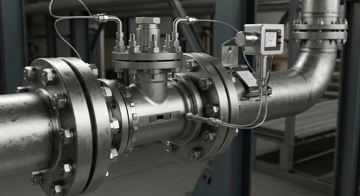
In my 20-plus years of commissioning piping systems across oil refineries and chemical processing plants, I have seen many flow measurement technologies come and go. Yet, the simple, rugged, and reliable differential pressure flowmeter remains the absolute workhorse of the industry. When you walk through any process facility, you will find these devices installed on steam lines, hydrocarbon feeds, and utility water systems.
Understanding how this device operates, how to select the correct plate geometry, and how to avoid common installation errors is fundamental for any piping or instrumentation engineer. In this guide, I will share my practical field experience and the technical calculations required to design and maintain these systems successfully.
Key Engineering Takeaways
- Standard Compliance: Always design and install systems in strict accordance with ISO 5167 and ASME MFC-3M.
- Beta Ratio Limits: Keep the beta ratio (d/D) strictly between 0.2 and 0.75 to maintain acceptable accuracy and limit permanent pressure loss.
- Tap Orientation: Orient pressure taps based on the fluid phase (top for gas, sides for liquids, and 45 degrees down for steam) to prevent debris or condensate accumulation.
- Straight Pipe Runs: Ensure adequate straight pipe lengths upstream and downstream to eliminate velocity profile distortions.
How Does an Orifice Flowmeter Measure Flow
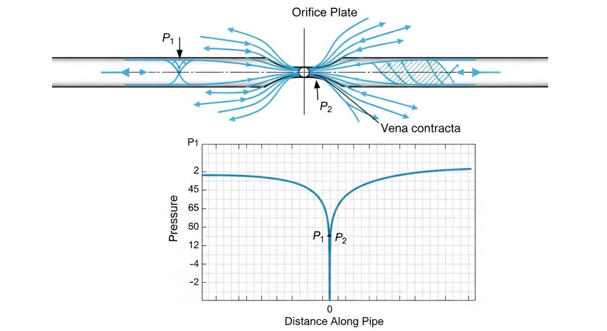
The physics behind this instrument is elegant. When a fluid flowing through a closed pipe encounters a restriction (the orifice plate), its velocity increases to maintain mass continuity. According to Bernoulli’s principle, this increase in kinetic energy causes a corresponding decrease in potential energy (static pressure).
The maximum velocity and minimum static pressure occur slightly downstream of the physical restriction, at a point called the vena contracta. By measuring the static pressure upstream of the plate and downstream at the vena contracta (or at designated tap locations), we obtain a differential pressure (DP) value.
The Flow Equation
The relationship between the volumetric flow rate and the differential pressure is expressed by the following standard equation:
Where:
- Q: Volumetric flow rate (cubic meters per second)
- C_d: Discharge coefficient (dimensionless, typically around 0.6 for sharp-edged plates)
- A_2: Cross-sectional area of the orifice bore (square meters)
- delta_P: Differential pressure across the plate (Pascals)
- rho: Fluid density at operating conditions (kilograms per cubic meter)
- beta: Beta ratio (d/D), which is the ratio of the orifice bore diameter (d) to the internal pipe diameter (D)
Because the flow rate is proportional to the square root of the differential pressure, a square root extractor must be applied in the control system (DCS/PLC) or within the smart multivariable transmitter to linearize the output signal.
In my career, I have resolved dozens of flow measurement discrepancies that were caused by a simple installation error: installing the orifice plate backward. Standard concentric plates have a sharp upstream edge and a beveled downstream edge. If the plate is installed with the bevel facing upstream, the discharge coefficient changes drastically, causing the transmitter to read up to 15% to 20% lower than the actual flow rate. Always verify that the stamped “INLET” or “UPSTREAM” marking on the plate handle faces the incoming flow.
Pressure Tap Configurations
The location of the pressure taps directly influences the discharge coefficient and the overall accuracy of the system. The three most common configurations defined by ISO 5167 are:
- Flange Taps: Located 1 inch (25.4 mm) upstream and 1 inch downstream from the plate faces. These are the most popular because they are integrated directly into the orifice flanges, eliminating the need to drill the pipe wall in the field.
- D and D/2 Taps: Located one pipe diameter (D) upstream and half a pipe diameter (D/2) downstream. This configuration is highly accurate as it places the downstream tap close to the vena contracta.
- Corner Taps: Located immediately adjacent to the plate faces on both sides. These are typically used for small pipe sizes (under 2 inches) where flange taps are physically impractical.
Selecting the Right Orifice Flowmeter Type
Not all process fluids behave the same way. Clean liquids, gases containing moisture, and slurries containing suspended solids require different plate geometries to prevent measurement errors and physical damage. The table below outlines the primary types of plates used in industrial piping.
| Plate Type | Bore Geometry | Primary Applications | Key Limitations |
|---|---|---|---|
| Concentric | Central circular hole with sharp upstream edge. | Clean liquids, dry gases, and low-velocity steam. | Prone to debris buildup; high permanent pressure loss. |
| Eccentric | Circular hole offset from the center, flush with pipe bottom or top. | Gases with entrained liquids (bore at top) or liquids with solids (bore at bottom). | Lower accuracy than concentric; complex calibration. |
| Segmental | Semicircular opening flush with the pipe wall. | Heavy slurries, sewage, and fluids with high solids content. | Reduced sensitivity; limited standard data available. |
| Quadrant Edge | Rounded upstream edge forming a quarter-circle profile. | Highly viscous fluids (crude oil, heavy syrups) at low Reynolds numbers. | Expensive to manufacture; highly sensitive to edge wear. |
To assist in the procurement and engineering design phase, I have compiled a comprehensive technical mapping matrix. This links physical parameters, standard codes, and typical industrial limits.
| Parameter / Entity | Acronym | Standard Value / Range | Reference Standard |
|---|---|---|---|
| Beta Ratio | beta (d/D) | 0.20 to 0.75 (Optimum: 0.4 to 0.6) | ISO 5167-2 |
| Reynolds Number Limit | Re | Greater than 5,000 (Concentric) | ASME MFC-3M |
| Permanent Pressure Loss | PPL | 40% to 90% of measured delta_P | Fluid Dynamics Handbook |
| Typical Accuracy | FS Acc. | Plus/Minus 1.0% to 2.0% of full scale | ISA-RP3.2 |
| Turndown Ratio | TDR | 3:1 to 4:1 (Up to 10:1 with stacked DP) | Manufacturer Specs |
Installing an Orifice Flowmeter Correctly
In my field audits, I have found that more than 70% of flowmeter measurement errors are caused by poor installation practices rather than instrument failure. If the velocity profile entering the orifice plate is distorted by upstream fittings, the differential pressure reading will be highly unstable and inaccurate.
Field Installation Checklist
-
Upstream Straight Run: Verify that a minimum of 10D to 40D (depending on beta ratio and upstream fittings) of straight, unobstructed pipe is present upstream of the plate.
-
Downstream Straight Run: Ensure at least 5D of straight pipe downstream of the plate to allow the flow profile to stabilize.
-
Gasket Alignment: Ensure gaskets do not protrude into the pipe bore. Protruding gaskets create turbulence and introduce significant measurement errors.
-
Drain/Vent Hole: If using a concentric plate for wet gas, ensure the drain hole is at the bottom. For liquid lines with entrained gas, ensure the vent hole is at the top.
-
Impulse Line Slope: Slope impulse piping at least 1:12 (8%) down toward the transmitter for liquid lines, or up for gas lines, to prevent pocketing of air or condensate.
Field Case Study: Real-World Application
The Problem: Unexplained Steam Balance Discrepancy
At a medium-sized chemical processing plant, the utility steam balance showed a persistent 12% discrepancy between the boiler house output and the main process reactor consumption. The reactor steam line utilized a concentric orifice plate with flange taps.
During my site inspection, I noticed that the differential pressure transmitter was mounted above the steam line with long, uninsulated impulse lines. Condensate was intermittently pooling in the impulse lines, creating a false hydrostatic head that skewed the DP readings.
The Solution: Re-Engineering the Installation
I supervised the following modifications during a planned weekend shutdown:
- Relocated the DP transmitter below the steam line to ensure the impulse lines remained completely filled with condensate.
- Installed condensate pots at the same elevation immediately adjacent to the orifice flanges.
- Replaced the worn concentric plate with a fresh, calibrated plate complying with ASME MFC-3M.
The Outcome
Once the system was restarted, the steam balance discrepancy dropped from 12% to less than 1.2%, well within the design tolerance of the plant. This simple physical correction saved the facility thousands of dollars in energy tracking errors and optimized the reactor’s thermal efficiency.
Frequently Asked Engineering Questions
What is the typical accuracy of an orifice flowmeter?
Why is the beta ratio kept between 0.2 and 0.75?
How do you prevent clogging in dirty fluid applications?
What is the difference between flange taps and D-D/2 taps?
Can an orifice flowmeter measure bidirectional flow?
How does fluid density variation affect measurement accuracy?
Complete Course on
Piping Engineering
Check Now
Key Features
- 125+ Hours Content
- 500+ Recorded Lectures
- 20+ Years Exp.
- Lifetime Access
Coverage
- Codes & Standards
- Layouts & Design
- Material Eng.
- Stress Analysis

Related posts:
![An engineer performing an API 579 fitness for service assessment on an industrial pressure vessel.]()
How to Perform API 579 Fitness for Service Assessment
![3D CAD render of a bolted flange joint assembly showing a compressed gasket.]()
Understanding Gasket m and y Factors in Flange Design
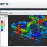
![PASS/START-PROF 4.86 pipe stress analysis software interface displaying a 3D piping model.]()
PASS/START-PROF 4.86 Released: Discover the New Pipe Stress Analysis Capabilities
![ASME certification mark stamped on an industrial pressure vessel nameplate]()
What is ASME Certification? Procedure and Mark Explained
![Professional technician inserting a high-pressure hydro jetting nozzle into a sewer pipe cleanout.]()
What is Hydro Jetting and How Does It Work?
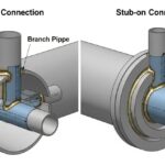
![Side-by-side comparison diagram of stub-in and stub-on piping branch connections.]()
Stub-in vs Stub-on Piping Connections: Engineering Design Guide