Engineering Guide to Non-Metallic Pipes in Industrial Applications
In my 20-plus years of troubleshooting piping failures across chemical plants and offshore platforms, I have seen millions of dollars literally rust away. Carbon steel and even high-grade stainless alloys struggle when handling aggressive acids, brackish water, or corrosive soils. That is where non-metallic options step in. But let me be clear: they are not a magic cure-all. If you design or install them using the same rules as metallic piping, you are setting yourself up for a catastrophic field failure. Thermoplastics and thermosets behave differently under thermal stress, pressure surges, and mechanical loading. In this guide, I will share the hard-won field insights and mechanical realities you must master to successfully deploy these materials.
What You Will Learn in This Guide
- How to select the correct thermoplastic or thermoset material based on chemical compatibility and temperature limits.
- The exact mechanical design calculations for thermal expansion and support spacing under ASME B31.3 Chapter VII.
- Critical field installation practices to prevent joint failures, solvent-welding errors, and over-tightening.
Designing Non-Metallic Pipes for High Pressures
Thermoplastic Pressure Rating: The maximum allowable working pressure of a plastic pipe is calculated using the Hydrostatic Design Basis modified by service design factors in accordance with ASTM D2837 and ASME B31.3. This methodology ensures that long-term hydrostatic strength is maintained over a projected fifty-year operational lifespan under varying thermal conditions.
Let us talk about the physics of thermoplastics. Unlike metals, which exhibit linear elastic behavior up to a distinct yield point, non-metallic materials are viscoelastic. This means their strength is highly dependent on both temperature and time. If you subject a PVC or HDPE pipe to a constant stress, it will deform continuously over time—a phenomenon known as creep.
To design safely, we use the ISO 12162 or ASTM D2837 standards to establish the Hydrostatic Design Basis (HDB). The Hydrostatic Design Stress (S) is calculated as:
S = (HDB * F)
Where F is the design factor (typically 0.5 for water or lower for hazardous chemicals under ASME B31.3 Chapter VII). The nominal pressure rating (PR) is then calculated using the classic Barlow’s Formula, modified for outside diameter (OD) and minimum wall thickness (t):
PR = (2 * S * t) / (D – t)
Where:
– PR = Pressure Rating (psi or MPa)
– S = Hydrostatic Design Stress (psi or MPa)
– t = Minimum Wall Thickness (inches or mm)
– D = Outside Diameter of the pipe (inches or mm)
Let us run through a real-world calculation. Suppose we are using an HDPE PE100 pipe with an Outside Diameter of 110 mm and a wall thickness of 10 mm (SDR 11). The HDB for PE100 at 20 degrees Celsius is 16 MPa. Using a design factor of 0.5, our Hydrostatic Design Stress (S) is:
S = 16 * 0.5 = 8 MPa
Now, we calculate the Pressure Rating:
PR = (2 * 8 * 10) / (110 – 10) = 160 / 100 = 1.6 MPa (16 bar)
If the operating temperature rises to 40 degrees Celsius, you must apply a thermal derating factor. For HDPE, the derating factor at 40 degrees Celsius is approximately 0.74. Thus, the adjusted pressure rating becomes:
Adjusted PR = 1.6 * 0.74 = 1.18 MPa (11.8 bar)
Ignoring this thermal derating is the number one cause of premature pipe bursts in industrial process lines.
CRITICAL FIELD WARNING: Water Hammer Vulnerability
Non-metallic piping systems have a much lower elastic modulus than steel, which actually helps absorb pressure surges. However, rapid valve closure can still generate shockwaves exceeding the pipe’s short-term burst pressure. Always limit liquid velocity to 1.5 meters per second (5 feet per second) and install slow-closing valves to prevent catastrophic surge failures in thermoplastic lines.
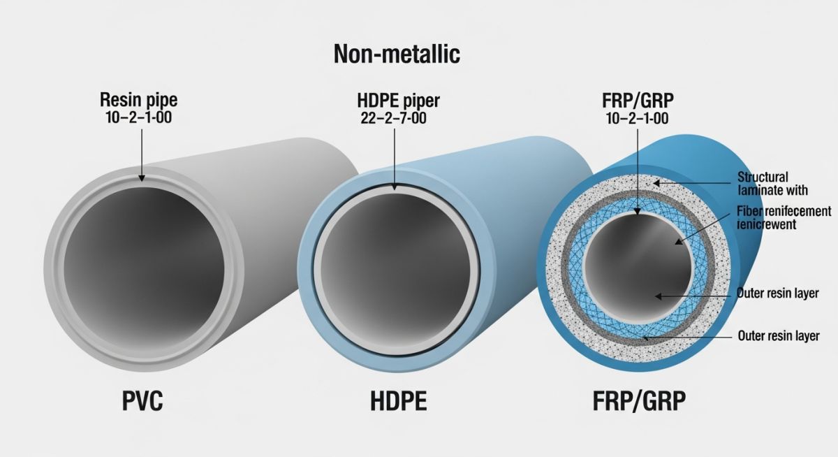
For higher pressures and temperatures, we turn to Fiber Reinforced Plastics (FRP) or Glass Reinforced Plastics (GRP). These are composite materials consisting of a polymer resin matrix reinforced with glass fibers. Designed under ASME B31.3 and ISO 14692, FRP pipes can handle pressures up to 50 bar and temperatures exceeding 100 degrees Celsius. The mechanical properties of FRP are highly anisotropic, meaning they depend on the winding angle of the glass fibers. A 55-degree winding angle is typically optimized to balance hoop stress and axial stress.
Physical Properties of Common Non-Metallic Materials
| Material Type | Max Temp (°C) | Elastic Modulus (GPa) | Thermal Expansion (10^-6/K) | Common Applications |
|---|---|---|---|---|
| PVC (Polyvinyl Chloride) | 60 | 3.0 | 80 | Water distribution, drainage, mild acids |
| CPVC (Chlorinated PVC) | 93 | 2.8 | 70 | Hot corrosive fluids, industrial waste |
| HDPE (High-Density Polyethylene) | 60 | 0.9 | 150 | Gas distribution, slurry lines, municipal water |
| PVDF (Polyvinylidene Fluoride) | 140 | 2.1 | 120 | Ultra-pure water, highly concentrated acids |
| FRP (Epoxy / Glass Fiber) | 110 | 15.0 – 25.0 | 20 | Seawater cooling, chemical process lines |
| Entity / Acronym | Full Technical Name | Primary Standard Reference | Key Design Parameter |
|---|---|---|---|
| HDB | Hydrostatic Design Basis | ASTM D2837 | Long-term hydrostatic strength at 100,000 hours |
| SDR | Standard Dimension Ratio | ASTM D2241 | Ratio of pipe outside diameter to wall thickness |
| FRP | Fiber Reinforced Plastic | ISO 14692 | Anisotropic structural strength and winding angle |
| MRS | Minimum Required Strength | ISO 12162 | Classified circumferential stress for plastic materials |
How to Install Non-Metallic Pipes Safely
Field Installation Protocol: The systematic verification of joint preparation, support spacing, and flange torque limits is mandatory to prevent mechanical failures in non-metallic piping systems. Adhering to ASME B31.3 Chapter VII installation guidelines ensures structural integrity and leak-free operation under design pressures.
Before you release a non-metallic piping system for commissioning, you must verify that the field crew followed specific installation procedures. Unlike steel, which can tolerate minor alignment errors and rough handling, plastics are unforgiving. A single over-tightened flange or a misaligned support can cause localized stress concentration, leading to sudden cracking.
Pre-Commissioning Field Checklist
- Support Spacing Verification: Ensure support spans match the specific thermoplastic material and operating temperature. Do not use narrow metal hangers that can cut into the pipe; use wide, flat bands.
- Flange Bolt Torque Control: Verify that all flange bolts are tightened in a star pattern using a calibrated torque wrench. Never exceed the manufacturer’s maximum torque limits to avoid crushing the plastic flange face.
- Solvent Joint Cure Times: For PVC and CPVC systems, confirm that the solvent-welded joints have cured completely based on ambient temperature and pipe size before hydrostatic testing.
- Thermal Expansion Allowance: Check that expansion loops, offsets, or guides are installed exactly as designed to allow the pipe to expand and contract without binding.
- Hydrostatic Test Pressure: Ensure the test pressure does not exceed 1.5 times the system design pressure, and never use compressed air or gas for leak testing thermoplastic lines.
Field Case Study: Real-World Application
The Problem: Catastrophic CPVC Header Failures
At a chemical processing facility in Texas, a newly installed Chlorinated Polyvinyl Chloride (CPVC) header carrying hot hydrochloric acid at 75 degrees Celsius began cracking at the joints within three weeks of startup. The engineering team initially blamed a defective batch of pipe. However, my field investigation revealed that the piping was rigidly anchored between two concrete walls without any expansion loops. The thermal expansion of CPVC at 75 degrees Celsius generated compressive stresses that far exceeded the material’s buckling limit, forcing the joints to shear.
The Outcome: Redesigning for Thermal Flexibility
I redesigned the system by introducing a series of L-bends and expansion loops calculated using the formula L = C * sqrt(D * delta_L), where C is the material constant for CPVC. We also replaced the rigid steel clamps with guide hangers lined with elastomeric pads to allow axial movement. Once these modifications were implemented, the system was pressure tested and returned to service. It has now operated for over five years without a single leak or crack, saving the client thousands of dollars in chemical loss and downtime.
Direct Recommendation: Always perform a formal thermal flexibility analysis for any thermoplastic piping system operating more than 20 degrees Celsius above ambient temperature. Never assume that plastic pipes can absorb their own thermal expansion without engineered loops or offsets.
Frequently Asked Engineering Questions
What is the difference between thermoplastic and thermosetting pipes?
How does temperature affect the pressure rating of plastic pipes?
Can non-metallic pipes be used for compressed air systems?
What is the maximum support spacing for HDPE piping?
How are joints made in FRP piping systems?
Why is UV protection necessary for outdoor plastic piping?
Complete Course on
Piping Engineering
Check Now
Key Features
- 125+ Hours Content
- 500+ Recorded Lectures
- 20+ Years Exp.
- Lifetime Access
Coverage
- Codes & Standards
- Layouts & Design
- Material Eng.
- Stress Analysis