Table of Contents

What Does an MEP Engineer Do? Roles, Responsibilities, and Salary
In my 20 years of managing complex industrial and commercial piping projects, I have seen countless designs succeed or fail based on one factor: the integration of mechanical, electrical, and plumbing systems. An MEP Engineer serves as the central nervous system of any construction project. Without their precise calculations, a building is nothing more than an empty concrete shell. They bridge the gap between architectural vision and physical reality, ensuring that water flows, electricity powers equipment safely, and air circulates efficiently.
When we look at modern high-rise structures or heavy industrial plants, the complexity of these systems is staggering. As an engineer who has spent decades in the field, I can tell you that a minor oversight in duct routing or electrical load balancing can delay a multi-million dollar project by months. Understanding the exact scope of this role is critical for developers, contractors, and aspiring engineers alike.
Key Takeaways from This Guide
- Discover the core responsibilities that define the daily workflow of an MEP professional.
- Learn the exact mathematical formulas used to size HVAC, electrical, and plumbing systems.
- Explore the current salary trends and career progression paths within the global construction industry.
Complete Course on
Piping Engineering
Check Now
Key Features
- 125+ Hours Content
- 500+ Recorded Lectures
- 20+ Years Exp.
- Lifetime Access
Coverage
- Codes & Standards
- Layouts & Design
- Material Eng.
- Stress Analysis
What Are the Core MEP Engineer Responsibilities?
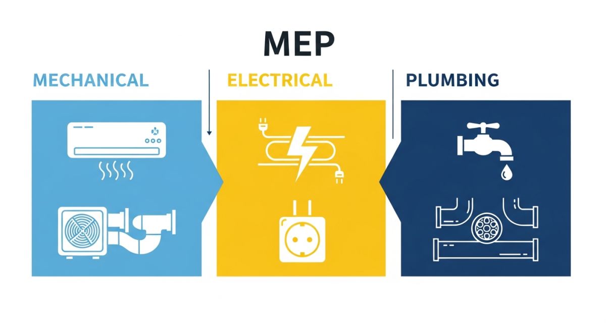
The daily responsibilities of an MEP professional span three distinct engineering disciplines. Each discipline requires adherence to specific international standards, such as those published by the American Society of Heating, Refrigerating and Air-Conditioning Engineers (ASHRAE), the National Fire Protection Association (NFPA), and the International Code Council (ICC).
1. Mechanical Systems (HVAC)
Mechanical design focuses primarily on thermal comfort and indoor air quality. I routinely calculate heating and cooling loads to size air handling units, chillers, and ductwork. A primary formula used to determine sensible cooling load is:
Where CFM represents the airflow rate in cubic feet per minute, and Delta T is the design temperature difference between the outdoor air and the desired indoor setpoint. For example, if a commercial zone requires 2,500 CFM of air and has a Delta T of 22 degrees Fahrenheit, the sensible cooling load is calculated as:
1.08 * 2,500 * 22 = 59,400 Btu/hr (or approximately 4.95 Tons of refrigeration).
2. Electrical Systems
Electrical design involves power distribution, lighting, and fire alarm systems. To size main distribution panels and feeders, we must calculate the total connected load and apply demand factors in accordance with the National Electrical Code (NEC). For a three-phase electrical system, the formula to calculate current is:
If we are sizing a feeder for a 45,000-Watt balanced three-phase load operating at 480 Volts with a power factor of 0.85, the calculation is:
45,000 / (480 * 0.85 * 1.732) = 63.7 Amperes. This value determines the minimum wire size and circuit breaker rating required to prevent thermal overload.
3. Plumbing and Piping Systems
Plumbing design covers potable water distribution, sanitary waste, storm drainage, and fire suppression. Sizing water supply lines requires converting fixture counts into Water Supply Fixture Units (WSFU) using Hunter’s Curve, as outlined in the International Plumbing Code (IPC).
In my experience, the most common field failures occur when mechanical ductwork, electrical cable trays, and gravity-fed plumbing lines attempt to occupy the same physical space. Gravity-fed plumbing lines must always take physical priority because their slope cannot be altered without compromising system drainage.
| System Category | Primary Design Parameter | Governing Code / Standard | Typical Field Metric |
|---|---|---|---|
| Mechanical (HVAC) | Air Exchange & Thermal Comfort | ASHRAE Standard 55 & 62.1 | 15 to 20 CFM per person |
| Electrical Power | Feeder Sizing & Overcurrent Protection | NFPA 70 (NEC) | 125% continuous load safety factor |
| Plumbing Systems | Fixture Unit Flow Rates | International Plumbing Code (IPC) | Max velocity 8 ft/s (water lines) |
| Fire Protection | Sprinkler Hydraulic Calculations | NFPA 13 | 0.10 to 0.20 GPM/sq. ft. density |
| Acronym | Full Technical Name | Physical Unit of Measure | Primary Application Area |
|---|---|---|---|
| CFM | Cubic Feet per Minute | Volumetric Flow Rate (ft³/min) | Ductwork sizing and air distribution |
| WSFU | Water Supply Fixture Unit | Dimensionless load value | Potable water pipe sizing |
| FLA | Full Load Amperes | Electric Current (Amperes) | Motor and equipment electrical supply |
| Btu/hr | British Thermal Units per Hour | Thermal Power (BTU/h) | Heating and cooling load calculations |
How Does an MEP Engineer Verify Site Readiness?
Before any major system is commissioned or enclosed behind drywall, I perform a rigorous physical walk-through. This checklist represents the minimum verification steps required to prevent costly field reworks and safety hazards.
Pre-Commissioning Field Checklist
-
Mechanical Duct Integrity
Verify that all duct joints are sealed with approved mastic or foil tape in accordance with SMACNA standards to prevent air leakage. -
Electrical Clearance Zones
Confirm a minimum of 36 inches of clear working space in front of all electrical panels and switchboards as mandated by NEC Article 110.26. -
Plumbing Slope & Venting
Measure the slope of horizontal sanitary drainage lines; ensure a minimum slope of 1/4 inch per foot for pipes 2 inches or smaller. -
Seismic Bracing & Supports
Inspect all overhead piping and ductwork runs to ensure seismic sway braces are installed according to local structural codes. -
Fire Barrier Penetrations
Verify that all pipes and ducts passing through rated firewalls are sealed with approved UL-listed firestop systems.
Field Case Study: Real-World Application
The Problem: Spatial Clash in a High-Rise Commercial Tower
During the construction of a 30-story commercial office building, a major spatial conflict was discovered on the 14th floor. A 600mm x 600mm main HVAC supply duct was designed to cross the exact same physical path as a high-voltage 400A electrical busway. The 2D drawings had failed to show the vertical elevations of these overlapping systems, resulting in a complete halt of installation work for both trades.
The Outcome: BIM Coordination & Rerouting
As the lead engineer, I immediately modeled the conflict area in Navisworks. Because the electrical busway could not be bent or easily rerouted due to strict voltage drop limitations, we redesigned the HVAC ductwork. We transitioned the 600mm x 600mm square duct into a wider, flatter 900mm x 400mm rectangular duct. This maintained the required cross-sectional area of 0.36 square meters, preserving the design airflow rate of 4,500 CFM without increasing static pressure.
This rapid engineering intervention resolved the clash within 48 hours, saving the client approximately 45,000 in field rework costs and preventing a projected two-week delay to the overall project schedule.
What Are the Average MEP Engineer Earnings?
Compensation in this field is highly competitive. Entry-level engineers typically start around 70,000 annually, while senior professionals holding a Professional Engineer (PE) license can easily command salaries exceeding 130,000, depending on the complexity of the projects they manage.
What qualifications are required to become an MEP Engineer?
How does BIM software impact the daily workflow of an MEP professional?
What is the difference between MEP design and MEP contracting?
Which codes govern plumbing design in commercial buildings?
Why is energy efficiency so important in modern MEP design?
What role does an MEP Engineer play in fire protection?

📚 Recommended Resources: MEP Engineer
Read these Guides


Related posts:
![Industrial worker welding a large structural steel I-beam in a fabrication facility.]()
What is Structural Steel Fabrication and How Does It Work?
![A heavy-duty stainless steel turnbuckle tensioning a structural cable.]()
What is a Turnbuckle and How to Install It?
![Stack of newly manufactured galvanized steel pipes in an industrial warehouse]()
Understanding the Galvanized Pipe Meaning in Modern Piping Systems
![Industrial Alloy 625 piping components in a manufacturing plant]()
What is Alloy 625? Properties, Grades, and Applications of Alloy 625
![Close-up of a fractured steel shaft showing metal fatigue beach marks and failure zones.]()
What is Metal Fatigue and How Do Engineers Prevent It?
![Industrial machinery fitted with smart sensors displaying real-time condition-based maintenance data on a digital overlay.]()
What is Condition-Based Maintenance and How Does It Work?