What are Industrial Scrubbers and How Do They Work
In my 20 years of piping and process plant design, I have seen many facilities struggle with emissions compliance. When a chemical plant or refinery vents process gases, you cannot simply let hazardous fumes escape into the atmosphere. That is where industrial scrubbers come into play. I have personally overseen the installation of massive wet scrubbing units in acid plants, and I can tell you that selecting the right scrubber is the difference between a smooth-running, compliant facility and millions of dollars in regulatory fines.
Scrubbers are the unsung heroes of industrial environmental engineering. They sit at the tail end of the process, taking in hot, dirty, and often highly corrosive flue gases and transforming them into clean, compliant exhaust. Whether you are dealing with sulfur dioxide, hydrochloric acid, or fine particulate matter, understanding the mechanics of these systems is critical for any piping or process engineer.
- Understand the fundamental phase-separation mechanics of wet and dry systems.
- Learn the critical liquid-to-gas ratio calculations that dictate scrubber efficiency.
- Identify the primary mechanical differences between packed bed and venturi designs.
- Review ASME and EPA compliance standards for industrial exhaust systems.
- Examine real-world field troubleshooting steps for pressure drop anomalies.
What are Industrial Scrubbers in Modern Plants
Industrial Emission Abatement: Industrial scrubbers are highly engineered process vessels that utilize liquid absorption or solid adsorption mechanisms to neutralize acidic gases, volatile organic compounds, and hazardous particulate matter from industrial flue gas streams.
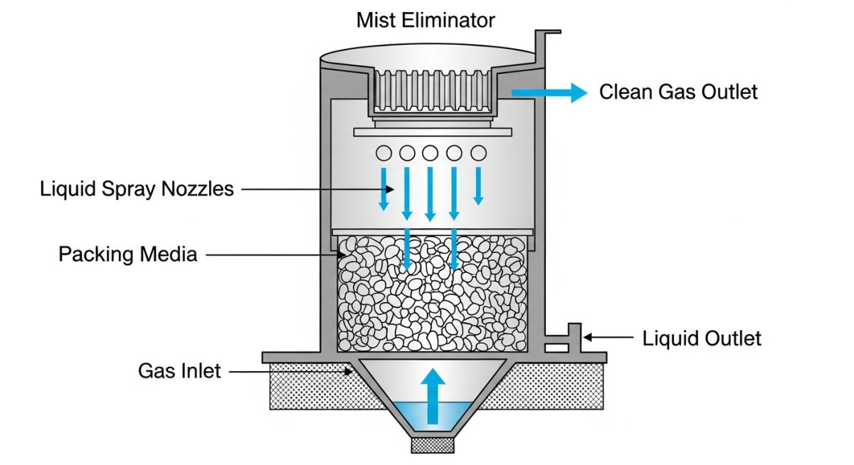
To truly understand what these systems do, we must look at the physical chemistry of mass transfer. In a typical wet scrubber, the dirty gas stream is forced through a vessel where it contacts a scrubbing liquid—usually water or a chemically reactive slurry. The pollutants are transferred from the gas phase to the liquid phase through absorption or chemical reaction.
Core Working Principles of Wet Scrubbers
Wet Scrubbing Mechanics: Wet scrubbers operate by bringing a contaminated gas stream into intimate contact with a scrubbing liquid, facilitating mass transfer of gaseous pollutants and inertial impaction of particulate matter into the liquid phase.
In my design practice, I focus heavily on the liquid-to-gas (L/G) ratio. This parameter determines the volume of liquid required per unit volume of gas to achieve the target removal efficiency. The formula for calculating the required liquid flow rate is:
Where:
Q_L = Liquid flow rate (gallons per minute)
Q_G = Gas flow rate (actual cubic feet per minute, ACFM)
L/G = Liquid-to-gas ratio (typically 10 to 40 gallons per 1,000 ACFM)
If your L/G ratio is too low, you will experience pollutant breakthrough because there is not enough liquid surface area to absorb the gas. Conversely, if it is too high, you will flood the column, causing an unacceptable pressure drop and liquid carryover.
Dry Versus Wet Scrubber Design Differences
Scrubber Design Comparison: Dry and wet scrubbers differ fundamentally in their reagent delivery systems, with wet systems utilizing liquid sprays and packed beds, while dry systems inject dry sorbents or atomized slurries that evaporate completely to produce a dry waste product.
Dry scrubbers are highly favored in plants where water availability is limited or where wastewater treatment costs are prohibitive. Instead of a liquid effluent, dry scrubbers produce a dry solid byproduct that can be collected using a downstream baghouse or electrostatic precipitator. This is highly common in coal-fired power plants for sulfur dioxide control, governed by EPA Clean Air Act Standards.
Key Advantages of Industrial Scrubber Systems
Scrubber Performance Benefits: Industrial scrubbers provide exceptional multi-pollutant control capabilities, enabling simultaneous removal of acid gases, toxic organic compounds, and fine particulate matter within a single compact footprint.
One of the biggest advantages of wet scrubbers is their ability to handle high-temperature, high-moisture gas streams without the risk of condensation or thermal shock, provided the materials of construction are correctly specified. They also offer a smaller physical footprint compared to dry baghouses of equivalent capacity.
The table below outlines the typical operating parameters and removal efficiencies for the three primary scrubber configurations used in heavy industry. These values are based on standard operating envelopes and comply with ASME Section VIII Design Codes.
| Scrubber Type | Target Pollutants | Typical Pressure Drop (in. W.C.) | L/G Ratio (Gal/1000 ACFM) | Removal Efficiency (%) |
|---|---|---|---|---|
| Packed Bed Wet Scrubber | Acid Gases (HCl, SO2, Cl2) | 2.0 – 6.0 | 10 – 25 | 98% – 99.9% |
| Venturi Scrubber | Fine Particulates (PM2.5, PM10) | 10.0 – 60.0 | 5 – 15 | 95% – 99% |
| Dry Sorbent Injector | Acid Gases (SO2, HF) | 4.0 – 8.0 (with Baghouse) | N/A (Dry Sorbent) | 90% – 97% |
This matrix maps the critical mechanical components of industrial scrubbers to their corresponding design standards and physical parameters.
| Component / Entity | Acronym | Key Physical Parameter | Applicable Standard |
|---|---|---|---|
| Fiberglass Reinforced Plastic Vessel | FRP | Tensile Strength, Corrosion Barrier | ASME RTP-1 |
| Flue Gas Desulfurization System | FGD | Slurry Density, pH Level | API Standard 560 |
| Mist Eliminator (Demister) | ME | Droplet Size Cutoff (microns) | EPA Method 5 |
Understanding What are Industrial Scrubbers and Systems
Scrubber Pre-Commissioning Protocol: Pre-commissioning verification involves systematic mechanical, hydraulic, and electrical checks of scrubber internals, spray patterns, and instrumentation to guarantee compliance with ASME RTP-1 and EPA emission limits.
Before introducing process gas into a newly installed scrubber, a rigorous verification protocol must be executed. In my experience, skipping these steps almost always results in nozzle plugging, poor distribution, or premature structural failure of the vessel internals.
-
Verify spray nozzle alignment and overlap to ensure 100% coverage of the packing bed. -
Inspect mist eliminator chevron plates for proper spacing and cleanliness. -
Check FRP vessel structural integrity and torque all flange bolts to ASME RTP-1 specifications. -
Calibrate differential pressure transmitters across the packing bed and venturi throat. -
Test pH control loop and chemical dosing pump calibration for acid neutralization. -
Confirm fan rotation direction and verify vibration levels are within ISO 10816 limits. -
Perform hydrostatic testing of the recirculation piping loop to identify joint leaks.
Field Case Study: Real-World Application
In my experience, continuous monitoring of both differential pressure and recirculating liquid pH is the single most effective way to prevent catastrophic scaling and maintain scrubber efficiency.
Frequently Asked Engineering Questions
What is the difference between a wet scrubber and a dry scrubber?
How do you calculate the liquid-to-gas (L/G) ratio for a wet scrubber?
What materials of construction are recommended for highly acidic scrubber environments?
What causes high pressure drop across a packed bed scrubber?
How does a venturi scrubber capture sub-micron particulate matter?
What are the primary EPA regulations governing industrial scrubber emissions?
Complete Course on
Piping Engineering
Check Now
Key Features
- 125+ Hours Content
- 500+ Recorded Lectures
- 20+ Years Exp.
- Lifetime Access
Coverage
- Codes & Standards
- Layouts & Design
- Material Eng.
- Stress Analysis

📚 Recommended Resources: Industrial Scrubbers
Related posts:
![Technician performing a hydrostatic shell test on a large industrial gate valve in a controlled laboratory environment.]()
Valve Inspection and Testing: Mastering API 598 Compliance Protocols
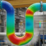
![3D digital model of thin-walled industrial piping showing stress distribution analysis in a professional engineering software environment.]()
Caesar II Stress Analysis for Thin-Walled Piping D/t Ratio Over 100
![Large vertical industrial pressure vessel showing nozzle connections and structural support skirt in a refinery setting.]()
Pressure Vessel Design: Engineering Standards, Materials, and Support Systems
![Industrial mechanical room showing large air handling units and complex ductwork for HVAC systems.]()
HVAC Systems Design: Objectives, Components, and Selection Criteria Explained
![3D engineering visualization of a piping system undergoing thermal expansion with stress concentration points highlighted in red and yellow.]()
Piping Flexibility Analysis: Essential Requirements for Safe Industrial Design
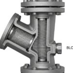
![Industrial Y-type piping strainer installed in a high-pressure steel pipeline with visible flanged connections and blow-off valve.]()
Piping Strainers: Design Standards, Selection Criteria, and Industrial Applications