Last Updated: May 2026
What are Hub & Clamp Connectors? | Design, Benefits, and Applications
I still remember a shutdown on an offshore module where a simple connector failure delayed startup by almost 18 hours. Not because the system design was wrong—but because the hub & clamp connector was mishandled during installation.
In theory, these connectors are marketed as quick, leak-proof, and maintenance-friendly. But in real plant conditions, I have seen them fail due to wrong seal selection, improper torqueing, and poor alignment control.
In this guide, I’ll walk you through how hub & clamp connectors actually work—not just from design manuals, but from what really happens on-site.
Key Takeaways
- Hub & clamp connectors provide compact, high-pressure sealing compared to bulky flanges.
- Seal ring selection directly impacts leak integrity under cyclic pressure.
- Improper bolt tightening sequence can cause misalignment and seal failure.
- They significantly reduce installation time and maintenance downtime.
- Widely used in offshore, subsea, LNG, and high-pressure gas systems.
Hub & clamp connectors are compact mechanical joints used in high-pressure piping systems where two hubs are clamped together using segmented clamps and bolts, with a metal seal ring ensuring leak-proof performance. They are widely used in oil & gas for faster installation, reduced weight, and improved reliability compared to conventional flange connections.
Quick Field Check: Hub & Clamp Connectors
1. What actually ensures leak-tight sealing in a hub connector?
Design of Hub and Clamp Connectors
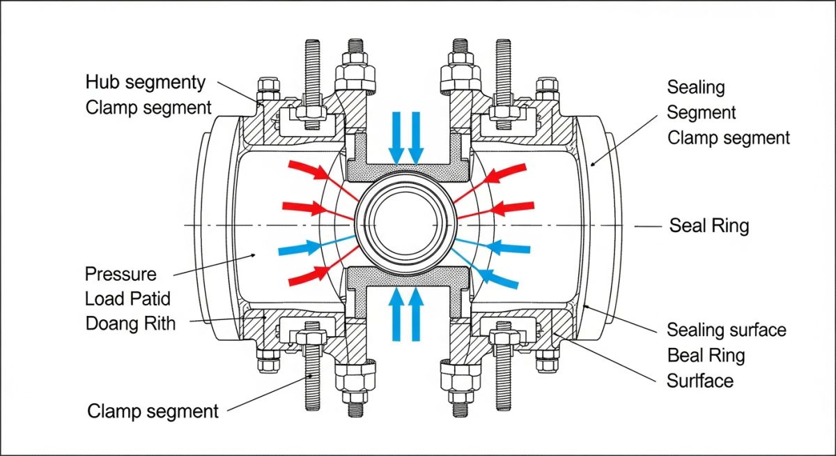
In my experience, a hub & clamp connector is not just a smaller substitute for a flange. I treat it as a precision preload-driven pressure joint. The sealing integrity comes from a very specific force path: internal pressure tries to separate the two hubs, the clamp segments convert bolt preload into radial and axial restraint, and the seal ring sits in a controlled geometry that allows metal-to-metal sealing under load.
When I review one of these joints, I check five things before I care about appearance: hub profile geometry, clamp segment fit-up, seal ring compatibility, bolt preload, and alignment tolerance. If one of these is off, the connector may still assemble, but it will not behave the way the designer intended once pressure and temperature cycles start.
Field warning
I have seen teams assume that a hub connector will “pull itself into line” once bolts are tightened. I never allow that assumption. If I force misaligned hubs together with bolt load, I can scar the seal faces, cock the seal ring, and create a leak path that only shows up during pressure ramp-up or thermal transients.
In the field, I break the design logic into three parts:
- Hub faces: I expect accurate machining, controlled seat geometry, and a sealing area free from dents, arc strikes, or handling damage.
- Clamp segments: I expect uniform contact on the hub shoulders so the external clamps can transform bolt tension into compressive clamping force.
- Seal ring: I expect material, hardness, and profile selection that match the service fluid, pressure class, temperature range, and cycling behavior.
I also calculate the joint in a practical way on site. Internal pressure creates a separating force approximated by F = P × Aeff, where P is system pressure and Aeff is the effective pressure area trying to push the hubs apart. For safe assembly, I want the net retained preload after losses from embedment, temperature change, and relaxation to remain higher than that separation demand. If I am close to the limit on paper, I know I am already at risk in real service.
Welding of Components
I pay close attention to the way the hub is attached to the piping component. Depending on the connector type, I may be looking at a weld-neck style hub, an integral forged hub, or a transition piece that has already been qualified for pressure-containing duty. My concern is not only strength. I also care about how welding heat input changes local metallurgy, distortion, hardness, and final alignment.
If I am dealing with carbon steel or low-alloy steel in sour or cyclic service, I review the weld procedure, heat treatment route, hardness acceptance, and NDE scope before I sign off the joint for service. If I skip this discipline, I may end up with a connector that is dimensionally acceptable but mechanically unreliable after repeated pressurization.
- I check whether the hub is forged as one piece or welded to a pup piece because that changes inspection scope.
- I verify root profile and cap contour where weld access is restricted by nearby clamps, supports, or pipe shoes.
- I review post-weld heat treatment requirements where the material grade or thickness demands it.
- I look for distortion that can shift the hub axis and turn a clean mechanical joint into an assembly fight.
Field warning
I never let grinding marks, temporary attachment scars, or weld spatter remain near the seal seating region. A tiny surface defect can act like a leak channel once the metal seal ring is energized. I have seen this happen even when hydrotest looked clean and the leak appeared only in gas service.
Placement of Bolts & Seal Ring
Bolt installation is where many teams lose the advantage of a compact connector. I install bolts with clean threads, verified lubrication, and a controlled tightening sequence. I do not chase final torque on one side and “balance later.” I build preload in passes, alternating positions so clamp segments seat evenly on both hubs.
For the seal ring, I inspect three conditions before assembly: correct orientation, untouched sealing surfaces, and traceable material grade. I do not reuse a seal ring unless the manufacturer’s guidance explicitly permits it and the service condition supports it. In most high-pressure work, I treat seal rings as controlled consumables because the cost of reuse is tiny compared with the cost of one leak, one hot bolting event, or one shutdown delay.
- I check seal ring seating depth and visual concentricity before I start tightening.
- I tighten in staged passes so clamp closure is uniform.
- I verify final bolt stretch or torque according to the approved procedure, not by feel.
- I recheck after hold time if the procedure calls for relaxation review.
Benefits of Using Hub & Clamp Connectors
I specify hub & clamp connectors where I want high pressure capability in a compact envelope. On offshore skids, compressed gas headers, subsea tie-ins, and dense modular packages, I often do not have the space or weight allowance for a large multi-bolt flange arrangement. A hub connector gives me a shorter joint length, lower envelope interference, and faster break-and-make work.
Where I see the biggest value
- Reduced installation footprint in tight pipe racks and modules
- Lower joint weight compared with heavy bolted flanges at similar duty
- Faster assembly during shutdowns and tie-in windows
- Reliable metal sealing in demanding pressure service
Where I stay cautious
- Damage tolerance is lower if handling discipline is poor
- Seal ring selection must match pressure, fluid, and temperature
- Assembly quality depends on trained fitters and controlled preload
- Spare philosophy must include the correct seal ring and bolting kit
But here is the catch: I only get these benefits if I protect the connector from casual assembly habits. If I treat it like a commodity fitting, I lose the time advantage in rework, leak testing, and shutdown extension.
Applications of Hub & Clamp Connectors
I usually recommend these connectors in services where pressure is high, access is restricted, and intervention cost is painful. In my work, that often means hydrocarbon production systems, gas compression packages, LNG equipment interfaces, chemical injection skids, subsea systems, and compact process modules where every millimeter matters.
- Offshore topsides: I use them where module space is tight and shutdown work must move quickly.
- Subsea connectors and trees: I value controlled geometry and predictable sealing when intervention cost is extreme.
- High-pressure gas lines: I prefer compact metal-sealed joints where flange envelopes become difficult to manage.
- LNG and cryogenic-adjacent systems: I review material toughness and seal behavior very carefully before acceptance.
- Brownfield retrofit projects: I use them where maintenance time reduction offsets the higher component cost.
Field warning
I do not treat every service as a candidate for hub connectors simply because the joint looks compact and premium. If fluid contamination, frequent abuse, poor access for controlled tightening, or weak maintenance discipline is expected, I reassess the choice.
Materials for Hub and Clamp Connectors
Material selection is one of the first places where I see hidden failures start. I choose hub, clamp, bolting, and seal materials as a system. I do not pick each item independently. Pressure rating, corrosion allowance, process chemistry, chloride exposure, H2S content, operating temperature range, and external environment all influence the final stack-up.
| Component | What I Commonly See | What I Check Before Approval |
|---|---|---|
| Hub | Carbon steel, low-alloy steel, stainless steel, duplex, nickel alloy | Pressure-temperature basis, toughness, weldability, sour-service suitability, corrosion resistance |
| Clamp | High-strength alloy steel or corrosion-resistant alloy depending on environment | Load transfer strength, coating system, stress corrosion risk, handling wear |
| Bolting | Studs and nuts selected for preload retention and compatibility | Lubrication basis, galling resistance, target preload, relaxation at temperature |
| Seal Ring | Metallic seal matched to service and hub geometry | Hardness pairing, corrosion compatibility, reuse policy, temperature cycling performance |
If I am working in sour service, I verify that the selected materials align with the project’s sour service philosophy and any applicable material restrictions. If I am in seawater-exposed offshore conditions, I also think about external corrosion, coating breakdown, trapped moisture, and maintenance handling damage. A good alloy choice can still fail if the assembly practice is careless.
Where standards are involved, I cross-check product and service requirements against the official frameworks that govern the equipment or the wider piping system, such as API, ISO, and ASME. I use the project specification hierarchy first, then I verify manufacturer certification and traceability against the governing purchase requirement.
Flange vs Hub Connector
I do not frame this as “which one is better” in the abstract. I frame it as which joint better fits the duty, space envelope, and maintenance plan. In many standard plant services, a flange remains easier to source, inspect, and maintain because the workforce knows it well and the site stores already support it. In compact high-pressure environments, a hub connector often gives me better packaging and faster intervention once the team is trained.
| Parameter | Conventional Flange | Hub & Clamp Connector | What I Usually Decide |
|---|---|---|---|
| Footprint | Larger envelope, more radial space | Compact envelope, lower radial congestion | I choose hub connectors in crowded modules and skid interfaces. |
| Assembly | More bolts, familiar site practice | Fewer external pieces, tighter preload control discipline | I choose flanges where workforce familiarity outweighs compactness. |
| Sealing Method | Gasket-based or ring-type depending on design | Metal seal ring within precision hub geometry | I favor hub connectors in high-pressure, leak-sensitive service. |
| Maintenance Duration | Can be longer due to bolt count and envelope | Often shorter if sealing kit and preload procedure are controlled | I check shutdown economics before I approve retrofit. |
| Standard Ecosystem | Broadly covered by general flange standards such as ASME | Often tied to specific product families and manufacturer qualification routes, sometimes under API/ISO product frameworks | I review project specs and vendor qualification very closely for hub connectors. |
Field Case Study: Brownfield Flange-to-Hub Retrofit on a Shutdown-Critical Gas Module
The Problem Statement
I handled a brownfield review where a high-pressure gas spool sat in a congested module corner with poor wrench swing, recurring maintenance delay, and repeated gasket replacement history. The existing flanged joint was not failing every cycle, but it was consuming too much shutdown time. Each intervention required extensive bolt handling, awkward access management, and repeated leak checks before restart approval.
I started by checking whether the service was a genuine candidate for retrofit. I reviewed pressure-temperature duty, fluid composition, vibration inputs, available spool flexibility, nozzle loads, and support behavior. I did not want to gain maintenance speed while creating a new load concentration or alignment problem.
After the mechanical review, I compared joint envelope, assembly access, and intervention sequence. The flange arrangement demanded greater radial space and too many individual bolt operations in a location where technicians had restricted posture and poor sight lines. A qualified hub & clamp connector reduced the working envelope and simplified the break-and-make sequence.
I then focused on the trap that many retrofit teams miss: preload accuracy and seal ring control. I built the installation method around alignment verification, seal ring traceability, controlled lubrication, staged tightening passes, and post-assembly hold verification. I also tied the retrofit package to the approved material specification and replacement spare kit so the site would not improvise with the wrong seal material later.
On the calculation side, I checked the effective separating load created by internal pressure, verified that the retained bolt preload margin stayed acceptable, and confirmed that adjacent supports would not induce cold spring or side loading during assembly. In the field, I never let the connector act as a fit-up correction tool.
Metric Outcome
- I cut the intervention sequence from a bolt-heavy flange operation to a faster controlled clamp assembly routine.
- I reduced access congestion around the joint envelope and improved tool handling posture for the maintenance crew.
- I removed recurring gasket replacement behavior and shifted the site toward a more disciplined seal ring management practice.
- I improved restart readiness because leak-check preparation became cleaner and more repeatable.
Field lesson learned: I only approve a flange-to-hub retrofit when I can prove that assembly discipline, spares control, and alignment management will improve with the change. If the site cannot protect seal rings, control preload, and store the right replacement kit, I keep the flange and solve the maintenance issue another way.
Technical Reference Points I Use During Review
I do not rely on memory alone when I review compact connector systems. I cross-check the project specification and vendor documents against the governing framework. Depending on service and equipment type, I may need to review:
- ASME reference documents for the surrounding piping philosophy and connected equipment basis.
- API product and equipment frameworks where wellhead, subsea, or high-pressure equipment interfaces are involved.
- ISO product and quality references when equipment qualification, manufacturing control, and interchangeability requirements are tied to project procurement.
- Vendor installation manuals for clamp segment orientation, seal ring identification, lubrication, and preload sequence.
- Project-specific material restrictions for sour service, chloride exposure, minimum design metal temperature, and external coating compatibility.
Frequently Asked Questions
Can I use a hub connector anywhere I currently use a flange? +
Do I reuse metal seal rings after opening the joint? +
What is the most common installation mistake I see? +
How do I decide the right material for the connector? +
Are hub connectors better for offshore work? +
What do I check before hydrotest or commissioning? +
Complete Course on
Piping Engineering
Check Now
Key Features
- 125+ Hours Content
- 500+ Recorded Lectures
- 20+ Years Exp.
- Lifetime Access
Coverage
- Codes & Standards
- Layouts & Design
- Material Eng.
- Stress Analysis
