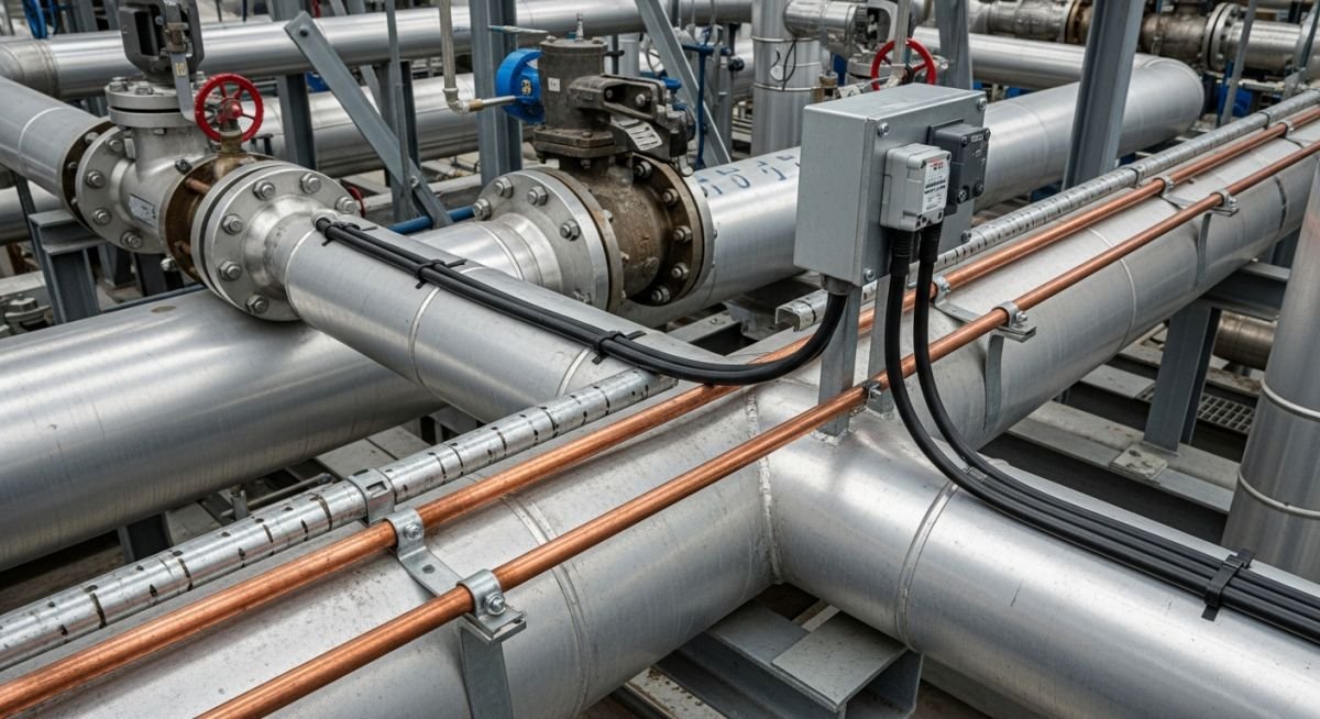
What is Heat Tracing? Steam Tracing vs Electric Tracing
In my two decades of piping design, I have seen countless projects derailed by improper thermal management. Heat tracing is not merely an accessory; it is the lifeblood of process continuity in cold climates or for high-viscosity fluids. Whether you are dealing with heavy fuel oils or sensitive chemical reagents, the choice between steam and electric tracing dictates your operational expenditure for the next twenty years.
I often remind junior engineers that heat tracing is a balance of thermodynamics and reliability. We are essentially fighting the ambient environment to maintain a specific process temperature. This guide breaks down the physics, the installation realities, and the decision-making framework I use to select the right system for complex industrial facilities.
Key Takeaways for Piping Engineers:
- Understand the heat loss calculation (Q = U * A * delta T) as the foundation for all sizing.
- Evaluate steam tracing for high-temperature applications where waste steam is readily available.
- Prioritize electric tracing for precise temperature control and lower maintenance overhead in remote areas.
- Always verify the maximum sheath temperature against the auto-ignition temperature of the process fluid.
Understanding Heat Tracing System Design Principles
Heat Tracing System Design: The systematic calculation of thermal energy requirements to offset heat loss through insulation, ensuring process fluids remain within specified temperature envelopes per IEEE 515 or IEEE 622 standards.
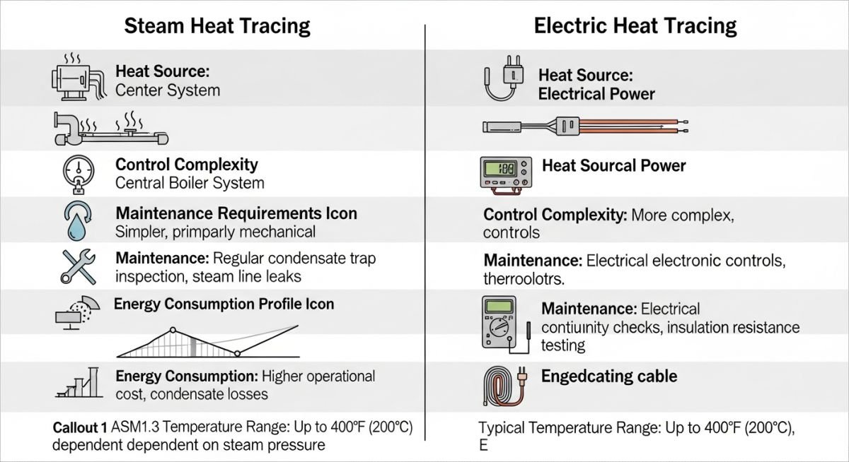
The core of any heat tracing design is the heat loss calculation. We define the required heat input (Q) as the product of the overall heat transfer coefficient (U), the surface area of the pipe (A), and the temperature differential (delta T) between the process fluid and the ambient air. In my experience, the most common failure point is underestimating the impact of wind velocity on the insulation surface.
When designing steam tracing, we utilize the latent heat of vaporization. The steam flows through a secondary tube (tracer) attached to the process pipe. The design must account for condensate removal; if the steam trap fails, the tracer becomes a heat sink rather than a source. I always specify stainless steel tubing for steam tracers to prevent corrosion-induced leaks that could contaminate the insulation.
Engineering Warning: Thermal Overheating
Never exceed the maximum allowable sheath temperature of your electric heating cable. If the process fluid is flammable, the cable temperature must remain below 80 percent of the auto-ignition temperature of the fluid, as mandated by NFPA 70 (NEC) hazardous area classifications.
Electric tracing, specifically Self-Regulating (SR) cables, offers a dynamic response to temperature changes. The conductive polymer core increases resistance as it heats up, effectively reducing power output. This is a massive advantage over constant-wattage cables, which require external thermostats to prevent overheating. However, SR cables have a limited circuit length, typically around 150 to 200 meters, which necessitates careful power distribution planning.
For high-temperature maintenance, such as molten sulfur or heavy bitumen, I often pivot to Mineral Insulated (MI) cables. These are rugged, can withstand temperatures up to 600 degrees Celsius, and are immune to the aging effects that plague polymer-based cables. The trade-off is the installation complexity; MI cables are rigid and require specialized termination kits that must be installed by certified technicians.
Heat Tracing Selection Trade-offs: A comparative analysis of operational reliability, capital expenditure, and maintenance intensity for steam versus electric thermal management systems.
Advantages
- Steam tracing utilizes existing plant utility infrastructure, reducing initial electrical load requirements.
- Electric tracing provides precise, localized temperature control via digital controllers and RTD sensors.
- Self-regulating electric cables eliminate the risk of localized hot spots without complex control logic.
- Steam systems are inherently explosion-proof, making them ideal for high-risk hazardous zones.
- Electric systems offer superior energy efficiency by only consuming power when the temperature drops below the setpoint.
Disadvantages
- Steam tracing requires extensive condensate return piping, increasing total installation weight and cost.
- Electric tracing is susceptible to voltage drops over long pipe runs, requiring intermediate power points.
- Steam leaks are difficult to detect and can cause severe insulation degradation and pipe corrosion.
- Electric systems require complex hazardous area certification (ATEX/IECEx) for all components.
- Steam tracing lacks the ability to modulate heat output, often leading to overheating of sensitive process fluids.
Industrial Heat Tracing Deployment: Strategic implementation of thermal maintenance systems across diverse process sectors to ensure fluid flow, prevent crystallization, and maintain chemical stability.
Refinery Heavy Fuel Oil Lines
In refinery operations, heavy fuel oils require constant temperature maintenance to prevent wax precipitation and viscosity spikes. I typically specify steam tracing for these long-distance transfer lines because the high thermal mass of the oil requires a robust, high-capacity heat source that steam provides efficiently.
Pharmaceutical Process Water Loops
Precision is the priority in pharmaceutical manufacturing, where process water must be kept at exact temperatures to prevent bacterial growth. Electric tracing with integrated PID controllers is the industry standard here, as it allows for tight temperature tolerances that steam systems simply cannot achieve.
Cryogenic Liquefied Gas Storage
While heat tracing is usually for heating, in cryogenic applications, we use it to prevent ice formation on valves and instrumentation. Low-wattage electric tracing is applied to prevent the ambient moisture from freezing and seizing mechanical components, ensuring that emergency shutdown valves remain operational in sub-zero conditions.
Caustic Soda Transfer Systems
Caustic soda solutions have a high freezing point and can become extremely viscous or solidify in cold weather. I recommend electric tracing with a high-temperature limit to ensure the solution remains fluid without reaching the boiling point, which would otherwise cause dangerous pressure buildup in the piping system.
Selecting the appropriate thermal maintenance system requires a rigorous evaluation of physical constraints and operational requirements. In my experience, the choice between steam and electric tracing is rarely about initial cost alone; it is fundamentally about the reliability of the utility supply and the specific heat requirements of the process fluid.
The following table outlines the critical engineering parameters that dictate system selection. When reviewing these values, consider the ASME B31.3 requirements for piping integrity, as improper heat tracing installation can lead to localized overheating or, conversely, cold spots that trigger crystallization or solidification of process media.
| Parameter | Steam Tracing | Electric Tracing |
|---|---|---|
| Heat Density | High (Variable via pressure) | Low to Medium (Controlled) |
| Control Precision | Low (Mechanical/Manual) | High (Electronic/PID) |
| Maintenance Intensity | High (Traps/Leaks) | Low (Monitoring/Testing) |
| Installation Complexity | High (Welding/Bending) | Moderate (Electrical/Termination) |
Engineers must prioritize the IEEE 515 standard for electric heat tracing to ensure that the power output matches the heat loss profile of the insulated pipe. Steam systems, while robust, require a comprehensive steam trap management program to prevent water hammer and condensate-induced corrosion, which can significantly shorten the service life of the piping system.
The following matrix maps the core technical entities involved in heat tracing design. Understanding these relationships is vital for maintaining compliance with international safety standards and ensuring that the thermal management system operates within the design envelope of the process piping.
Each entity listed below represents a critical node in the design lifecycle, from the initial heat loss calculation to the final commissioning of the control panel. I have found that failing to account for the interaction between these variables often leads to premature system failure or excessive energy consumption during winterization cycles.
| Entity | Standard/Ref | Primary Function |
|---|---|---|
| Self-Regulating Cable | IEEE 515 | Dynamic heat output adjustment |
| Steam Trap | ASME PTC 39 | Condensate removal/Energy efficiency |
| Thermal Insulation | ASTM C168 | Heat loss minimization |
| Control Panel | NEC Article 427 | System monitoring and safety |
By aligning these components with the referenced standards, you create a robust framework for process temperature maintenance. Always verify that the insulation material is compatible with the maximum sheath temperature of the heating element to prevent degradation or fire hazards in hazardous area classifications.
Heat Tracing System Validation: Before energizing or introducing steam to a newly installed heat tracing system, a rigorous site verification process is mandatory. This checklist ensures that the installation meets the design intent and safety requirements defined in IEEE 515 and ASME B31.3.
- ☐ Insulation Integrity: Verify that all insulation is dry, properly sealed, and free of gaps that could lead to convective heat loss.
- ☐ Electrical Continuity: Perform a Megger test (insulation resistance) to ensure no short circuits exist between the heating element and the pipe wall.
- ☐ Steam Trap Functionality: Confirm that all steam traps are installed at the lowest points and are free of debris or blockage.
- ☐ Sensor Placement: Ensure temperature sensors are located at the furthest point from the heat source to prevent premature cycling.
- ☐ Hazardous Area Compliance: Check that all junction boxes and terminations meet the required ATEX or IECEx ratings for the specific zone.
In my experience, the most common failure point is the lack of proper documentation regarding the “as-built” configuration. Ensure that every circuit is tagged with its design temperature and power rating. If you encounter a discrepancy between the design heat loss and the actual measured temperature, re-evaluate the insulation thickness and the ambient temperature assumptions used in the initial calculation.
Field Case Study: Real-World Application
Problem: Chronic Steam Trap Failure in a Chemical Processing Plant
- Excessive condensate accumulation led to severe water hammer in the steam tracing lines.
- Inconsistent process temperatures caused product crystallization in the downstream piping.
- High maintenance costs due to frequent replacement of mechanical steam traps.
- Corrosion under insulation (CUI) detected at multiple pipe support locations.
Outcome: Transition to Self-Regulating Electric Heat Tracing
- Eliminated water hammer risks by removing the steam utility requirement entirely.
- Achieved a 15% reduction in energy consumption through precise PID-controlled heating.
- Reduced annual maintenance labor hours by 60% due to the removal of mechanical traps.
- Improved process stability, resulting in a 5% increase in overall production yield.
The recommendation for similar facilities is to conduct a life-cycle cost analysis before committing to steam. While steam is effective for high-temperature applications, the operational overhead of maintaining a steam distribution network often outweighs the initial capital expenditure of an electric system.
Frequently Asked Engineering Questions
How do I calculate the required heat density for a pipe?
- Identify the pipe diameter, insulation thickness, and thermal conductivity of the insulation material.
- Calculate the temperature difference between the process fluid and the minimum expected ambient temperature.
- Apply the heat loss formula based on ASTM C680 to determine the watts per meter required.
- Include a safety factor of 10 to 20 percent to account for wind chill and insulation degradation over time.
What are the primary risks of steam tracing?
- Water hammer: Condensate buildup can cause severe pressure surges that damage piping and fittings.
- Overheating: Steam at high pressure can exceed the temperature limits of the process fluid, leading to degradation.
- Leakage: Steam leaks are not only energy-intensive but also pose significant safety hazards to personnel.
- Corrosion: The presence of moisture and oxygen in the tracing system accelerates external corrosion of the carrier pipe.
When should I choose self-regulating cables?
- They automatically adjust their heat output based on the surrounding pipe temperature.
- They can be overlapped without the risk of burnout, simplifying installation on complex piping geometries.
- They are highly energy-efficient as they only consume power when the pipe temperature drops below the set point.
- They are the preferred choice for freeze protection in non-critical process lines.
How does insulation affect heat tracing performance?
- High-quality insulation reduces the total heat loss, allowing for lower power consumption or lower steam pressure.
- Properly sealed insulation prevents moisture ingress, which is the primary cause of thermal performance degradation.
- The thickness of the insulation must be optimized to balance capital cost against long-term energy savings.
- Always use materials that are chemically compatible with the process fluid in the event of a leak.
What is the role of a temperature controller?
- They monitor the pipe temperature via RTD or thermocouple sensors.
- They switch the power to the heating cable on or off based on the measured temperature.
- Advanced controllers offer alarm functions for high or low temperature conditions, enhancing system safety.
- They allow for remote monitoring and integration into the plant’s distributed control system (DCS).
Are there specific standards for hazardous areas?
- All components must be certified for the specific zone (e.g., Zone 1 or Zone 2) as per IEC 60079.
- The maximum sheath temperature of the heating cable must be lower than the auto-ignition temperature of the surrounding gases.
- Ground fault protection is mandatory for all electric heat tracing circuits in hazardous locations.
- Regular inspections are required to ensure that the integrity of the explosion-proof enclosures is maintained.
📚 Recommended Resources: Heat Tracing
Read these Guides
🎓 Advanced Training



Complete Course on
Piping Engineering
Check Now
Key Features
- 125+ Hours Content
- 500+ Recorded Lectures
- 20+ Years Exp.
- Lifetime Access
Coverage
- Codes & Standards
- Layouts & Design
- Material Eng.
- Stress Analysis
