Gas Insulated Switchgear Footprint Rules: SF6 vs AIS Sizing
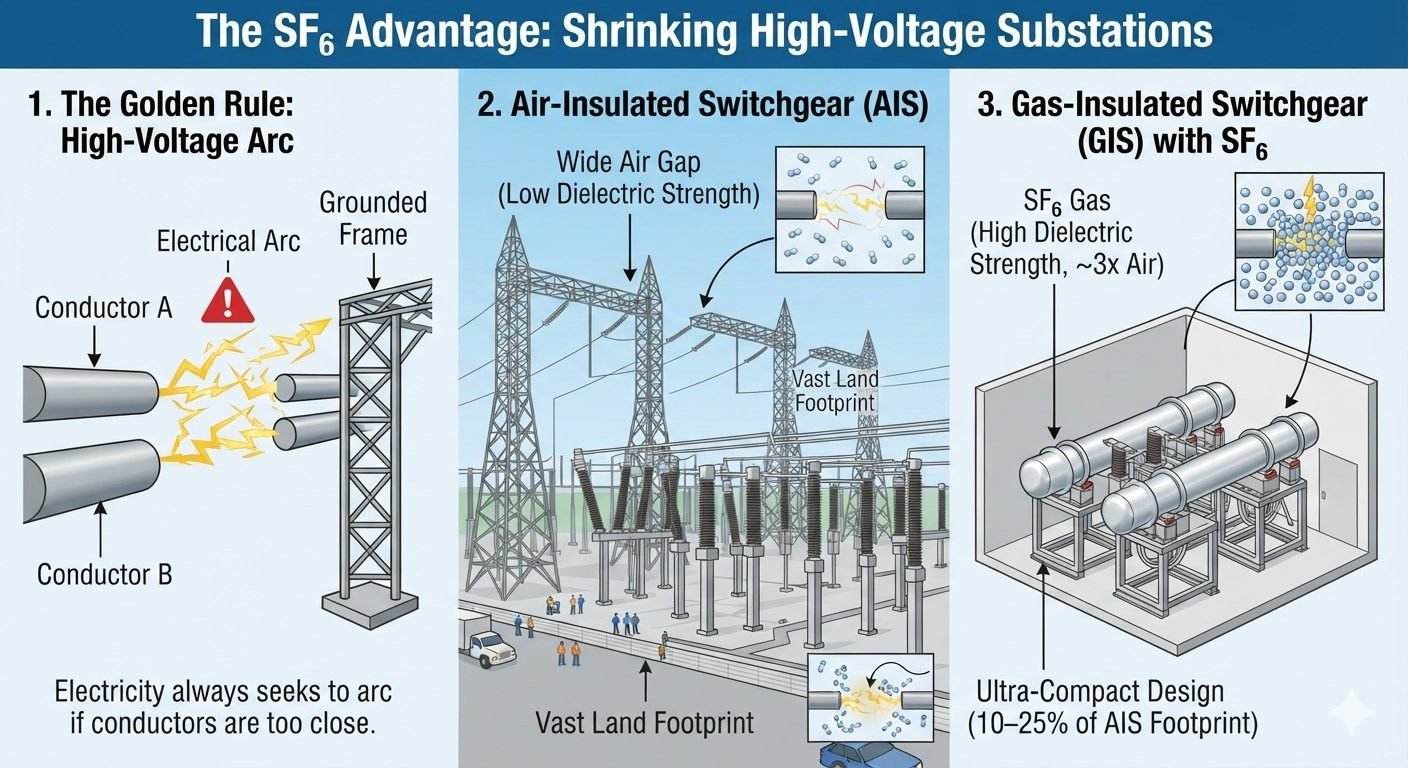
Over my 20-plus years designing substation layouts and plant piping interfaces, I have watched high-voltage substation boundaries shrink dramatically. In early civil projects, laying out an Air-Insulated Switchgear (AIS) yard required spanning thousands of square meters of open land just to prevent phase-to-ground flashover across air gaps.
Transitioning to compact high-voltage equipment changes the spatial dynamic entirely. Understanding how the gas insulated switchgear footprint compresses physical plant dimensions requires looking directly at the underlying dielectric physics of sulfur hexafluoride ($SF_6) versus atmospheric air.
Key Takeaways for Substation Layout Engineers
- Dielectric Advantage: Pressurized $SF_6 gas exhibits nearly three times the electronegativity of atmospheric air at base pressure, allowing clearance distances to shrink by order of magnitude.
- Footprint Compression: Total switchgear land consumption drops from 100% in conventional AIS installations to 10–25% in equivalent GIS configurations.
- Civil Impact: Massively reduced site grading, shorter busbar routing, reduced structural steel work, and complete containment from atmospheric contaminants.
Dielectric Physics and Gas Insulated Switchgear Footprint Mechanics
In high-voltage engineering, atmospheric air under ambient pressure acts as a baseline dielectric insulator. However, air possesses a relatively low breakdown strength of approximately 3 kV/mm under uniform field conditions. When voltage surges cross a conductor gap, air ionizes rapidly, creating a conductive plasma channel that causes catastrophic flashover.
To prevent flashover in Air-Insulated Switchgear (AIS), live conductors must be separated by substantial spatial clearance. Phase-to-phase and phase-to-ground distances expand exponentially as system operational voltages scale from 145 kV up to 500 kV.
Paschen’s Law and Breakdown Field Equations
The breakdown voltage ($V_b$) of a gas-filled gap is governed by Paschen’s Law, which expresses breakdown potential as a function of the product of gas pressure ($p$) and gap distance ($d$):
Where $A$ and $B$ represent composition-specific gas constants, and $gamma_{se}$ represents the secondary electron emission coefficient. Atmospheric air operates at ambient pressure (1.013 text{ bar}$ abs). In contrast, Gas-Insulated Switchgear utilizes sulfur hexafluoride ($SF_6) sealed at elevated working pressures ranging between 4.5 text{ bar}$ and 6.0 text{ bar}$ gauge.
$SF_6 is a strongly electronegative gas. Its molecules capture free electrons during early ionization stages, forming heavy, stable negative ions. This electron attachment process prevents electron avalanche growth, giving $SF_6 roughly 2.5 to 3 times the dielectric breakdown strength of air at equal pressure. When pressurized to 5 bar, the effective dielectric strength of $SF_6 increases by more than 10 times relative to ambient air.
Mathematical Calculation: Clearance Distance Comparison
Consider a 145 kV system rated for a Basic Impulse Insulation Level (BIL) of 650 kV peak withstand voltage. We calculate the minimum required phase-to-ground gap distance for both atmospheric air and pressurized $SF_6.
- Air Clearance Calculation: With an air operational stress threshold of $E_{air} approx 0.5 text{ kV/mm}$ (incorporating safety factors and non-uniform field geometry factors under IEEE Std 1427):
d_{air} = frac{BIL}{E_{air}} = frac{650 text{ kV}}{0.5 text{ kV/mm}} = 1300 text{ mm} quad (1.3 text{ meters clear distance})
- SF6 Clearance Calculation: With pressurized $SF_6 at 4.5 bar gauge offering a practical safe withstand stress limit of $E_{SF6} approx 18 text{ kV/mm}$:
d_{SF6} = frac{BIL}{E_{SF6}} = frac{650 text{ kV}}{18 text{ kV/mm}} = 36.1 text{ mm} quad (0.036 text{ meters clear distance})
This drastic reduction in required insulating gap translates directly to structural bay layout dimensions. An AIS 145 kV bay requires a minimum width of 9.0 to 10.0 meters to accommodate phase isolation gaps and maintenance access walkways. The equivalent GIS 145 kV feeder module requires a bay width of only 1.2 to 1.5 meters.
Optimizing Gas Insulated Switchgear Footprint in Substation Design
Compressing the physical footprint affects more than just the equipment dimensions. It changes the structural foundation load distribution, cable duct trenching, and busbar containment engineering.
Field Engineering Warning: Density Management
Because GIS compact design relies on gas pressure to maintain dielectric breakdown strength, any loss of density collapses the breakdown threshold. Gas monitoring density switches calibrated to ISO 14040 standards must trigger automatic trips before pressure drops below critical minimum levels.
When engineering a substation boundary, shrinking phase spacing reduces total civil land acquisition needs by up to 90 percent. A standard 400 kV AIS substation bay occupies roughly 4,200 square meters. An equivalent 400 kV GIS bay fits within a footprint of just 380 square meters.
Design Advantages
- • Land Area Savings: Shrinks total substation land area requirement by 75% to 90%, making urban and industrial installation economically viable.
- • Environmental Immunity: Enclosed gas compartments protect internal busbars, breakers, and disconnectors from coastal salt spray, industrial soot, and ice accumulation.
- • Seismic Stability: Lower overall center of gravity and rigid aluminum enclosure housings provide superior resistance against seismic shock waves.
- • Minimal Maintenance: Sealed primary contacts reduce contact oxidation, extending routine internal maintenance intervals up to 20 years.
- • Personnel Safety: Grounded metallic enclosures completely eliminate open electric field exposure and risk of accidental physical contact.
Design Disadvantages
- • Higher Capital Cost: Initial procurement expenditures for aluminum enclosures, pressure sensors, and precision machining run 1.5 to 2.5 times higher than standard AIS equipment.
- • SF6 Management: Requires dedicated gas monitoring systems, leak-detection sensors, and strict handling protocols due to high Global Warming Potential.
- • Extended Outage Times: Internal arc faults require specialized evacuation, gas filtering, structural dismantling, and cleanroom vacuum drying before recommissioning.
- • Thermal Dissipation: Enclosed gas design limits passive heat dissipation, requiring careful conductor sizing to manage thermal expansion.
- • Civil Enclosure Needs: Indoor GIS layouts require specialized indoor building infrastructure with heavy overhead crane capacity for maintenance access.
1. Dense Urban Center Infill Substations
Municipal power utilities installing high-voltage supply nodes inside metropolitan city centers face massive land acquisition costs. Deploying indoor gas-insulated switchgear lets engineers integrate a complete 230 kV substation within a standard multi-story commercial building footprint, bypassing open-air yard clearance requirements entirely.
2. Offshore Substation Platforms
Offshore wind energy collector platforms incur extreme structural steel construction costs per square meter of deck area. Compact GIS layouts minimize deck platform sizing while housing high-voltage breakers inside sealed, salt-spray-resistant gas enclosures designed to withstand harsh marine environments.
3. Chemical & Heavy Industrial Facilities
Petrochemical refineries and fertilizer manufacturing complexes contain corrosive chemical vapors and atmospheric particulates that trigger flashover on exposed air-insulated bushings. GIS systems isolate all primary conductors within pressurized metallic casings, preventing chemical corrosion and flashover trip events.
4. Mountainous Mining Operations & High Altitude Sites
At high elevations, reduced atmospheric air density significantly lowers air breakdown voltage, forcing conventional AIS designs to widen phase clearances even further. Sealed GIS compartments maintain constant internal gas density regardless of ambient atmospheric elevation pressure, preserving optimal footprint efficiency.
In high-voltage engineering, physical dimensions are dictated directly by the breakdown voltage of the insulating medium. Atmospheric air requires expansive spatial isolation to prevent flashovers during lightning impulses and switching surges. When evaluating substation layouts across transmission voltage tiers, comparing Air-Insulated Switchgear (AIS) against Gas-Insulated Switchgear (GIS) reveals how dielectric medium density governs real estate requirements.
The table below presents standardized dimensional requirements derived from IEC 60071-1 for insulation coordination and IEEE C37.122 for gas-insulated systems. These values highlight the dramatic footprint compression achieved when substituting atmospheric air with pressurized sulphur hexafluoride (SF6) gas at standard operating pressure (0.45 to 0.60 MPa relative).
| Nominal System Voltage (kV) | Insulation Medium | Phase-to-Earth Clearance (mm) | Phase-to-Phase Clearance (mm) | Standard Bay Width (m) | Bay Land Area Requirement (m²) | Footprint Reduction (%) |
|---|---|---|---|---|---|---|
| 145 kV | Air (AIS) | 1,300 | 1,500 | 10.0 | 260 | Baseline (0%) |
| 145 kV | SF6 Gas @ 0.45 MPa (GIS) | 160 | 180 | 1.5 | 22.5 | 91.3% |
| 245 kV | Air (AIS) | 2,200 | 2,500 | 17.0 | 680 | Baseline (0%) |
| 245 kV | SF6 Gas @ 0.50 MPa (GIS) | 240 | 280 | 2.0 | 56.0 | 91.7% |
| 420 kV | Air (AIS) | 3,400 | 4,000 | 24.0 | 1,440 | Baseline (0%) |
| 420 kV | SF6 Gas @ 0.60 MPa (GIS) | 380 | 450 | 3.0 | 144.0 | 90.0% |
Note: Land area per bay figures include access aisles, maintenance clearances, and structural support footprints. Actual field values vary slightly based on busbar configuration (single vs. double busbar layouts).
Designing compact high-voltage switchgear requires systematic coordination across mechanical, electrical, and gas-handling parameters. In my 20+ years of substation design, I have observed that improper component matching often leads to localized electric field enhancements, premature partial discharge, or unnecessary site expansion.
The specification matrix below details core engineering entities, structural components, governing standards, and key physical parameters that make high-density gas insulation possible.
| Technical Component | Governing Standard | Key Operating Parameter | Material / Medium | Design Impact on Substation Area |
|---|---|---|---|---|
| Enclosure Cylinder | IEC 62271-203 | Pressure Rating: 0.7 MPa burst test | Cast Aluminum Alloy / Stainless Steel | Provides ground potential shield, allowing zero phase-to-phase air spacing externally. |
| Insulating Gas Medium | IEC 60376 | Dielectric Strength: ~89 kV/cm at 0.1 MPa | Pure SF6 (Sulfur Hexafluoride) | Reduces clearance distances by up to 85% compared to atmospheric air gap rules. |
| Disconnector & Fast Earth Switch | IEC 62271-102 | Making Capacity: 40 kA peak (Fast Earth) | Silver-Plated Copper Contacts | Integrated inside SF6 chamber, eliminating external open-air isolator structure. |
| Conductor Support Spacer | IEC 62271-203 | PD Level: < 2 pC at 1.25 Um | Alumina-Filled Epoxy Resin | Mechanically anchors conductor within enclosure without requiring massive post insulators. |
| Gas Density Monitor | IEEE C37.122 | Alarm Threshold: 0.40 MPa relative | Temperature-Compensated Bellows | Maintains exact molecular density to safeguard compact clearances dynamically. |
Gas insulated switchgear site verification: Electrical clearance inspection, SF6 gas purity testing, and enclosure alignment must strictly adhere to IEC 62271-203 to ensure full dielectric strength across compact busbars.
Before finalizing a high-voltage substation footprint design or accepting GIS equipment on site, field engineers must execute strict quality assurance steps. The high dielectric stress inside pressurized gas compartments leaves zero room for geometric misalignment or gas contamination. Below is the field site verification protocol I follow on major substation projects.
Substation Layout & GIS Commissioning Checkpoints
Verify foundation slab levelness within ±2 mm over a 10-meter span. Gas-insulated modules are rigid metallic structures; foundation unevenness creates mechanical stress on enclosure flanges and internal epoxy spacers.
Test filled SF6 gas according to IEC 60376. Ensure dew point under pressure is below -15°C and moisture content does not exceed 15 ppmv. Water molecules in high-field regions drastically lower dielectric breakdown strength.
Perform UHF partial discharge monitoring at 1.1 times rated operating voltage per IEC 62271-203. Confirm background noise stays below 2 pC to ensure no metallic slivers or installation dust remain inside the gas chamber.
Check ground connections at every enclosure joint. High-voltage switching operations generate Very Fast Transients (VFT). Low-impedance multi-point grounding is mandatory to prevent transient enclosure voltages (TEV) from shocking field personnel.
Confirm gas barrier spacers isolate distinct gas compartments correctly. Verify burst disc directional orientation and deflection paths face away from personnel walkways in compliance with local utility safety standards.
Field Case Study: Real-World Application
In dense urban environments, land acquisition represents the largest capital hurdle for high-voltage grid expansions. The following engineering case study examines a real-world transmission substation upgrade where site constraints forced a complete shift from conventional air-insulated architecture to high-density gas-insulated switchgear.
The Problem: Severe Urban Site Constraints
A regional utility needed to construct a new 230 kV intertie substation in a densely populated industrial district with strict spatial limitations.
- Available land footprint was strictly limited to 1,200 square meters by adjacent properties.
- Traditional 230 kV AIS open-air design required minimum phase clearances of 2.2 meters to ground and 2.5 meters between phases.
- Standard six-bay AIS double-bus configuration required over 6,500 square meters of horizontal real estate.
- Adjacent chemical processing plant presented severe air pollution and salt deposition risks, threatening open-air insulator integrity.
Engineering Assessment: Building an open-air AIS layout was physically impossible on the plot and would require expropriating five neighboring commercial buildings at exorbitant cost.
The Outcome: 88% Footprint Reduction via Indoor GIS
The engineering team converted the technical specification to a indoor 230 kV Gas-Insulated Switchgear layout operating at 0.5 MPa relative pressure.
- Six GIS bays were installed inside a compact two-story building occupying just 720 square meters of ground footprint.
- Achieved an overall footprint reduction of 88.9% compared to the 6,500 square meter baseline AIS proposal.
- Total capital cost decreased by 18% when accounting for avoided urban land acquisition expenses.
- SF6 sealed enclosure eliminated flashover risks caused by industrial pollution, reducing maintenance intervals from annual to 10-year cycles.
Final Recommendation: When urban real estate costs exceed 300 per square meter, the higher equipment cost of GIS is completely offset by property savings, delivering lower total lifecycle expenditure.
Frequently Asked Engineering Questions
Complete Course on
Piping Engineering
Check Now
Key Features
- 125+ Hours Content
- 500+ Recorded Lectures
- 20+ Years Exp.
- Lifetime Access
Coverage
- Codes & Standards
- Layouts & Design
- Material Eng.
- Stress Analysis
