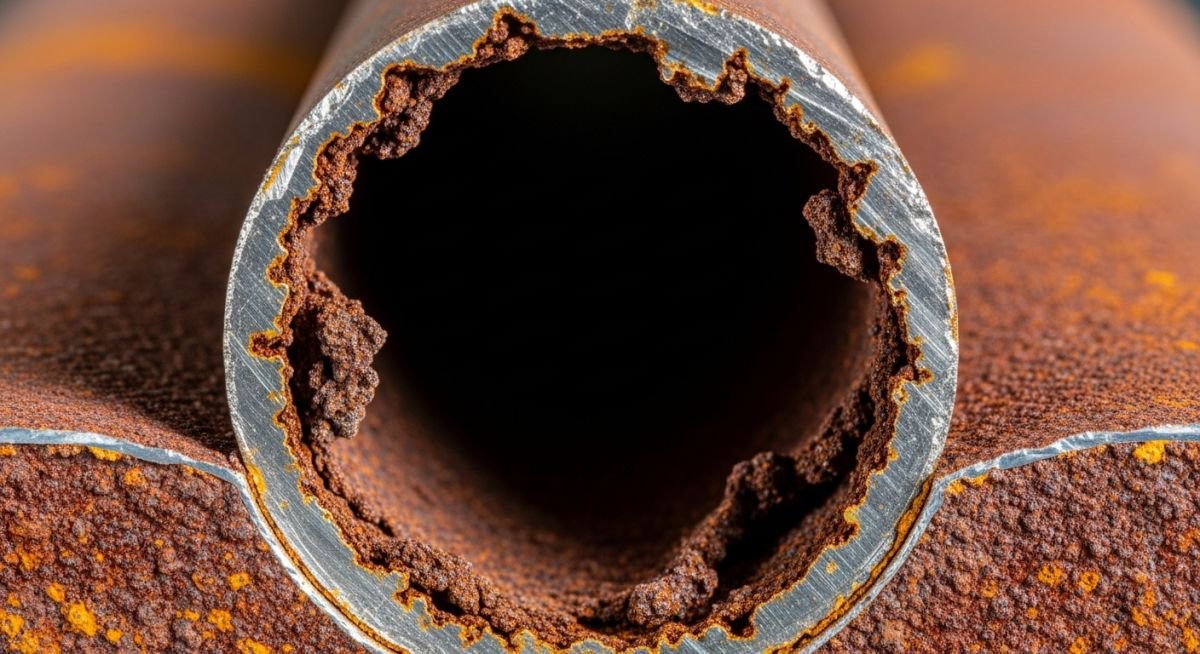
Understanding the Primary Forms of Corrosion in Industrial Piping
In my two decades of field experience, I have seen multi-million dollar projects derailed by the silent, relentless progression of material degradation. Understanding the specific forms of corrosion is not merely an academic exercise; it is the cornerstone of asset integrity management. Whether dealing with high-pressure hydrocarbon lines or aggressive chemical processing units, the ability to identify the morphology of metal loss determines whether a system remains operational or suffers a catastrophic failure.
This guide dissects the primary mechanisms that threaten our infrastructure. We will move beyond basic oxidation to explore localized pitting, stress-induced cracking, and flow-accelerated degradation, providing you with the technical framework to implement robust mitigation strategies that comply with global engineering codes.
Key Takeaways
- Distinguish between uniform thinning and localized pitting mechanisms.
- Apply NACE MR0175/ISO 15156 for sour service material selection.
- Implement cathodic protection and chemical inhibition based on environmental pH and temperature.
- Utilize ASME PCC-2 for repair and mitigation of corroded pressure components.
Technical Analysis of Forms of Corrosion
Corrosion Mechanisms: The fundamental electrochemical processes involving anodic dissolution and cathodic reduction, which dictate the rate of material loss in metallic piping systems.
To engineer reliable piping, one must first quantify the electrochemical potential. Uniform corrosion, while predictable, is often managed through corrosion allowance (CA) as defined in ASME B31.3. However, localized forms of corrosion—such as pitting and crevice corrosion—present significantly higher risks because they occur at rates orders of magnitude faster than uniform thinning. Pitting is characterized by the breakdown of the passive film, often triggered by chloride ions in stagnant conditions.
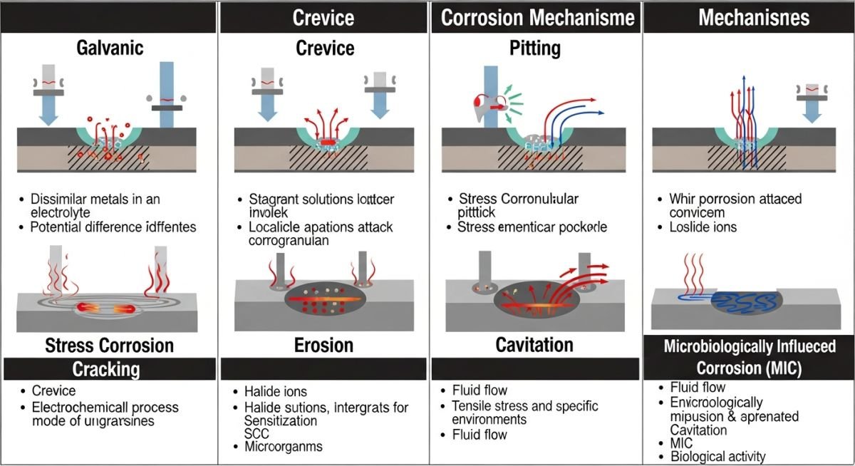
When evaluating stress-related degradation, we must consider Stress Corrosion Cracking (SCC). This occurs when tensile stress, a susceptible material, and a specific corrosive environment (e.g., caustic or amine) coexist. The crack propagation rate is often modeled using fracture mechanics, where the stress intensity factor (K) must remain below the threshold (K_ISCC) to prevent sudden brittle failure. In my experience, the most dangerous scenarios involve hydrogen-induced cracking (HIC) in sour service, where atomic hydrogen diffuses into the steel lattice, accumulating at inclusions and causing internal blistering.
Field Warning: Flow-Accelerated Corrosion (FAC)
FAC is frequently overlooked in high-temperature carbon steel piping. It occurs when the protective magnetite layer is dissolved by high-velocity fluid, leading to rapid wall thinning. Always verify the chromium content of your piping materials; even small additions (0.1% Cr) can significantly improve resistance to FAC in single-phase flow environments.
Calculation of the corrosion rate (CR) is typically expressed in millimeters per year (mm/y) or mils per year (mpy). The formula is derived from Faraday’s Law: CR = (K * W) / (A * T * D), where K is a constant, W is mass loss, A is area, T is time, and D is density. In practice, we use ultrasonic thickness (UT) measurements to trend these rates. If the measured rate exceeds the design allowance, we must pivot to material upgrades (e.g., moving from A106 Gr. B to 316L Stainless Steel) or implement chemical inhibition programs.
Corrosion Mitigation Strategies: The systematic evaluation of material selection, chemical treatment, and design modifications to minimize the lifecycle cost of industrial piping assets.
Advantages of Proactive Mitigation
- Extended asset service life beyond the original design cycle.
- Reduced risk of environmental contamination and regulatory fines.
- Lowered insurance premiums through documented integrity management programs.
- Optimized maintenance schedules based on real-time corrosion monitoring data.
- Improved safety profiles by preventing high-pressure process leaks.
Disadvantages and Implementation Challenges
- High initial capital expenditure for corrosion-resistant alloys (CRAs).
- Complexity in managing chemical injection systems and inhibitor residuals.
- Increased weight of piping systems when using thicker walls for corrosion allowance.
- Difficulty in detecting subsurface cracking without advanced NDT techniques.
- Potential for galvanic corrosion when joining dissimilar metals in the field.
Industrial Corrosion Management: The application of material science and engineering standards to protect critical infrastructure across diverse process sectors.
Upstream Oil and Gas Production
In sour gas fields, managing hydrogen-induced cracking is paramount. Engineers specify materials compliant with NACE MR0175 to ensure the steel microstructure resists hydrogen embrittlement under high partial pressures of H2S.
Chemical Processing and Refining
Refineries utilize high-alloy piping to combat naphthenic acid corrosion and high-temperature sulfidation. Proper material selection, such as 5Cr-0.5Mo or 9Cr-1Mo steels, is essential for maintaining integrity in distillation units.
Desalination and Water Treatment
Seawater intake lines face severe pitting and crevice corrosion due to high chloride concentrations. Engineers often employ duplex stainless steels or cathodic protection systems to prevent premature failure of thin-walled piping components.
In my two decades of field experience, I have found that selecting materials based solely on nominal pressure ratings is a recipe for premature failure. Understanding the specific Forms of Corrosion requires a rigorous mapping of environmental stressors against metallurgical thresholds. The following table categorizes common degradation mechanisms, providing a baseline for engineers to evaluate material compatibility under ASME B31.3 and NACE MR0175 guidelines.
When reviewing this data, note that the “Primary Driver” column indicates the dominant electrochemical or mechanical catalyst. For instance, while chloride stress corrosion cracking is often associated with stainless steels, the presence of specific temperature gradients can accelerate the propagation rate by orders of magnitude. Always cross-reference these findings with your site-specific fluid analysis reports to ensure that trace contaminants do not shift the material into a higher risk category.
| Mechanism | Primary Driver | Susceptible Material | Standard Reference |
|---|---|---|---|
| Pitting | Localized Chloride Attack | Austenitic Stainless Steel | ASTM G48 |
| SCC | Tensile Stress + Environment | Duplex Stainless Steel | NACE MR0175 |
| Galvanic | Dissimilar Metal Potential | Carbon Steel to Copper | ASTM G82 |
| Erosion | Fluid Velocity/Particulates | Carbon Steel (Elbows) | API RP 14E |
This matrix serves as a starting point for your integrity management program. If your process fluid contains hydrogen sulfide or high-temperature chlorides, you must move beyond these general classifications and perform a detailed metallurgical assessment to prevent catastrophic loss of containment.
Effective asset management relies on the precise identification of degradation entities. This matrix maps the physical parameters of various Forms of Corrosion to their respective industry-standard mitigation strategies. By aligning your maintenance intervals with these specific technical entities, you can significantly reduce the probability of failure (PoF) across your piping network.
Engineers should utilize this mapping to standardize inspection reports. When a field inspector identifies a specific morphology, such as “trenching” or “intergranular attack,” this matrix provides the direct link to the governing code requirements. This ensures that the corrective action taken is not just a temporary patch but a code-compliant restoration of the piping system’s design life.
| Entity | Acronym | Key Parameter | Mitigation Code |
|---|---|---|---|
| Hydrogen Induced Cracking | HIC | pH and H2S partial pressure | NACE TM0284 |
| Microbiologically Influenced | MIC | Sulfate-reducing bacteria count | NACE SP0106 |
| Flow Accelerated Corrosion | FAC | Mass transfer coefficient | API 571 |
Always remember that these parameters are interdependent. For instance, a change in fluid velocity (FAC) can strip away protective biofilms, potentially altering the environment for MIC. A holistic view of these entities is required for robust piping integrity.
Verification of Forms of Corrosion in the field requires a systematic approach to data collection and visual inspection. I have developed this checklist to ensure that no critical indicator is overlooked during routine integrity audits. Use this to validate that your current mitigation strategies are actually performing as intended under real-world operating conditions.
-
Baseline Thickness Mapping: Verify that current ultrasonic testing (UT) data matches the original baseline thickness recorded during commissioning per API 570. -
Insulation Integrity: Inspect for signs of CUI (Corrosion Under Insulation) by checking for moisture ingress at jacket seams and pipe supports. -
Cathodic Protection Potential: Confirm that the pipe-to-soil potential meets the minimum -850 mV (CSE) requirement for buried assets. -
Chemical Injection Rates: Validate that corrosion inhibitor dosage matches the current fluid chemistry analysis and flow velocity profiles. -
Dead-Leg Assessment: Identify all stagnant zones where sediment accumulation could trigger localized pitting or MIC.
If any of these items fail verification, you must immediately initiate a root cause analysis (RCA). Do not simply increase chemical dosage; investigate whether the material selection itself is fundamentally incompatible with the current process fluid composition. Document all findings in your asset management software to maintain a clear audit trail for regulatory compliance.
Problem: Unexpected Pitting in Stainless Steel Manifold
- Rapid wall thinning observed in 316L stainless steel piping after only 18 months of service.
- Process fluid contained trace chlorides at temperatures exceeding 60 degrees Celsius.
- Stagnant conditions in the manifold allowed for chloride concentration at the metal surface.
- Lack of proper drainage design led to localized pooling during system shutdowns.
Outcome: Successful Mitigation and Material Upgrade
- Replaced 316L components with Super Duplex stainless steel to improve pitting resistance equivalent (PREN).
- Implemented a mandatory flushing procedure to remove stagnant fluids during maintenance cycles.
- Installed high-point vents and low-point drains to ensure complete system drainage.
- Reduced failure rate to zero over the subsequent 48-month monitoring period.
My recommendation for similar scenarios is to prioritize material selection based on the PREN (Pitting Resistance Equivalent Number) calculation. Never assume that standard 300-series stainless steel is sufficient for process fluids containing chlorides, especially in systems with potential for temperature spikes or stagnant flow.
How does fluid velocity influence erosion-corrosion?
- High velocities cause turbulence, particularly at elbows and tees, leading to localized wall thinning.
- The presence of solid particulates in the fluid stream significantly accelerates this mechanical degradation.
- Engineers must refer to API RP 14E to calculate the erosional velocity limit for specific piping materials.
- Maintaining flow below these critical thresholds is the primary defense against this form of degradation.
What is the role of NACE standards in material selection?
- NACE MR0175 defines the metallurgical requirements for materials used in sour service environments.
- Compliance ensures that hardness levels and heat treatment processes are controlled to prevent brittle failure.
- These standards are mandatory for many oil and gas applications to ensure safety and regulatory compliance.
- Failure to adhere to these specifications can lead to catastrophic, sudden rupture of pressure-containing components.
Can cathodic protection prevent all forms of corrosion?
- It cannot protect the internal surfaces of piping unless the fluid itself is conductive and the system is designed for it.
- It does not mitigate stress corrosion cracking or erosion-corrosion mechanisms.
- Over-protection can lead to hydrogen embrittlement in high-strength steels.
- Regular monitoring of potential levels is required to ensure the system remains within the protective window.
How do I identify Microbiologically Influenced Corrosion (MIC)?
- Laboratory analysis of water samples for sulfate-reducing bacteria (SRB) is a key diagnostic step.
- Visual inspection often reveals a distinct “volcano” shape in the corrosion product.
- It frequently occurs in stagnant or low-flow areas where bacteria can colonize the pipe wall.
- Mitigation involves biocidal treatment and regular pigging to remove biofilms.
What is the difference between pitting and crevice corrosion?
- Pitting occurs on exposed surfaces due to localized breakdown of the passive film.
- Crevice corrosion occurs in shielded areas, such as under gaskets, bolt heads, or lap joints.
- Crevice corrosion is driven by the depletion of oxygen within the restricted space.
- Both require careful material selection and design to minimize stagnant zones.
Why is CUI a major concern for insulated piping?
- Moisture trapped between the insulation and the pipe wall creates an ideal environment for rapid corrosion.
- It is particularly severe in cyclic temperature services where condensation occurs.
- Effective mitigation requires high-quality cladding and regular inspection of insulation seals.
- Refer to API 583 for comprehensive guidance on CUI management and inspection strategies.
📚 Recommended Resources: Forms of Corrosion
Read these Guides


Complete Course on
Piping Engineering
Check Now
Key Features
- 125+ Hours Content
- 500+ Recorded Lectures
- 20+ Years Exp.
- Lifetime Access
Coverage
- Codes & Standards
- Layouts & Design
- Material Eng.
- Stress Analysis
