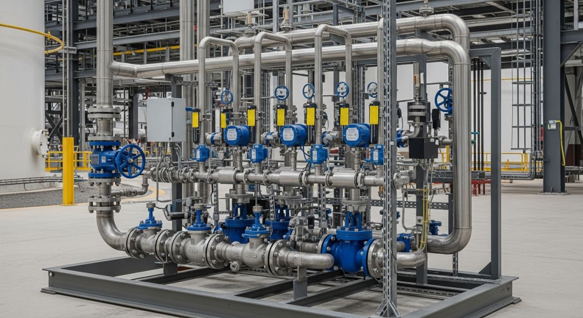
Understanding the Flow Metering Skid: Design and Precision
In my two decades of piping engineering, I have found that the flow metering skid is the heartbeat of any hydrocarbon processing facility. It is not merely a collection of pipes and valves; it is a precision-engineered assembly designed to ensure that every drop of product is accounted for with absolute financial and operational integrity.
Whether you are dealing with cryogenic LNG or high-pressure crude oil, the skid must maintain laminar flow profiles and minimize turbulence to ensure the primary measurement elements—be they Coriolis, ultrasonic, or turbine meters—perform within their specified uncertainty limits.
Key Takeaways for Engineering Success:
- Strict adherence to API MPMS standards for custody transfer.
- Modular design reduces field welding and site installation time.
- Integration of flow computers for real-time density and pressure compensation.
- Importance of upstream and downstream straight pipe runs for flow conditioning.
Technical Deep-Dive: Flow Metering Skid Design Parameters
Flow Metering Skid Design: The systematic integration of mechanical piping, instrumentation, and control logic to achieve precise volumetric or mass flow measurement within defined uncertainty tolerances.
Designing a flow metering skid requires a rigorous approach to fluid dynamics. The primary objective is to maintain a fully developed velocity profile at the meter inlet. According to ASME B31.3, the piping layout must account for thermal expansion and vibration, which can introduce measurement errors if not properly mitigated through structural support and stress analysis.
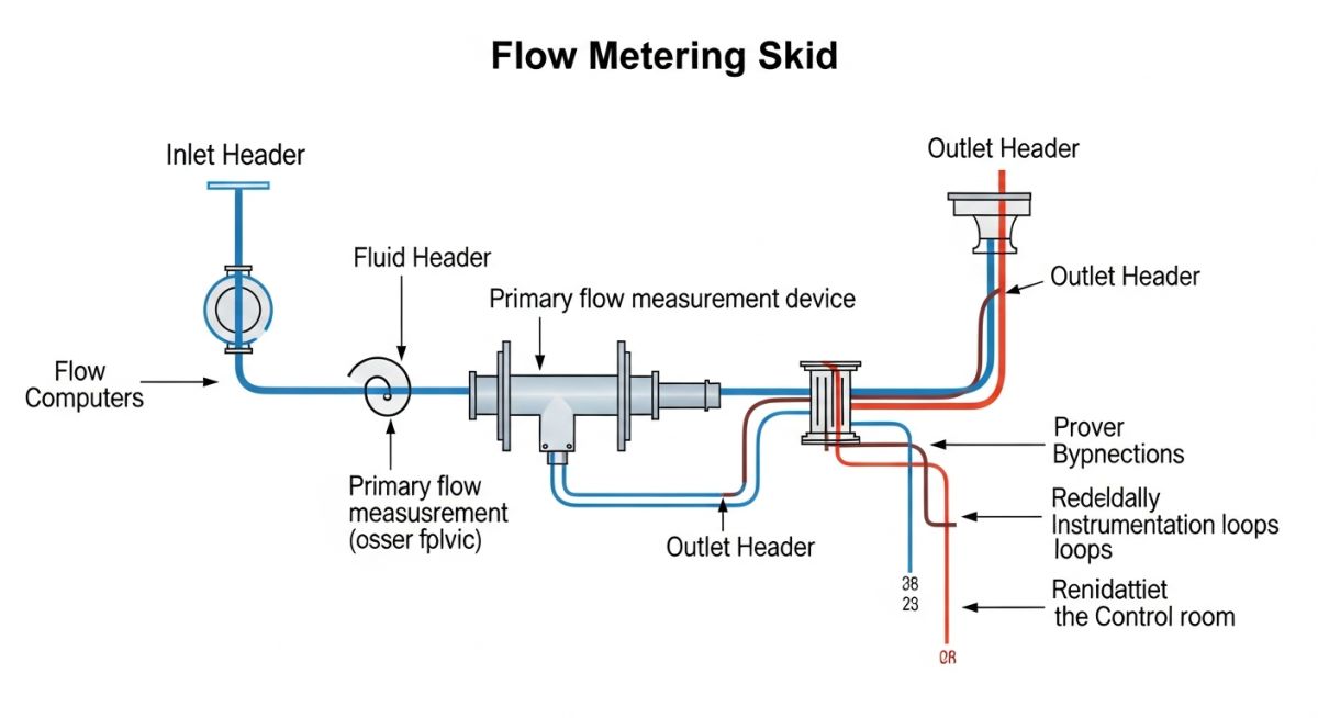
Fluid Dynamics and Metering Accuracy
The Reynolds number is the governing factor in our design. For most liquid metering applications, we target a Reynolds number exceeding 4000 to ensure turbulent flow, which is more predictable for meter calibration. We utilize flow conditioners, such as the Zanker or tube bundle types, to eliminate swirl and asymmetry caused by upstream elbows or control valves.
Field Warning: The Turbulence Trap
Never place a control valve or a partially closed isolation valve within 10 pipe diameters upstream of the flow meter. The resulting vortex shedding will cause significant measurement drift and potential damage to the meter internals, leading to non-compliance with API Chapter 5.
Calculation of Meter Run Lengths
To calculate the required straight pipe length, we use the formula L = K * D, where D is the nominal pipe diameter and K is a factor determined by the upstream piping configuration (e.g., single elbow, double elbow out of plane). In practice, I always recommend a minimum of 20D upstream and 5D downstream to provide a safety margin for meter performance.
Pressure drop across the skid is another critical parameter. We calculate the total pressure loss using the Darcy-Weisbach equation, ensuring that the cumulative loss across the meter, strainer, and valves does not exceed the pump’s available head. If the pressure drop is too high, we must increase the pipe diameter or select a meter with a lower pressure drop coefficient.
Metering Skid Performance: A balanced assessment of modular skid implementation versus traditional stick-built piping systems in industrial environments.
Advantages
- Factory-controlled welding environments ensure higher NDT pass rates.
- Reduced site footprint and faster installation schedules.
- Pre-commissioning and FAT (Factory Acceptance Testing) minimize site rework.
- Standardized design allows for easier spare parts management.
Disadvantages
- High initial transportation costs for large, oversized skid modules.
- Limited flexibility for site-specific piping modifications post-delivery.
- Requires heavy-lift equipment for final positioning on foundations.
- Complex interface management between skid piping and plant tie-ins.
Industrial Metering Deployment: Strategic implementation of flow metering skids across diverse energy and chemical processing sectors.
Custody Transfer of Crude Oil
These skids are the primary fiscal measurement point between pipeline operators and refineries. They utilize high-accuracy Coriolis or ultrasonic meters to calculate mass flow, ensuring financial equity based on precise density and temperature compensation.
Natural Gas Distribution Networks
In gas transmission, metering skids manage high-pressure flow from processing plants to regional grids. These systems often include gas chromatographs for real-time energy content analysis, which is vital for billing based on calorific value.
Chemical Feedstock Blending
Metering skids are used in chemical plants to precisely control the ratio of different feedstocks entering a reactor. By maintaining strict flow control, these skids ensure consistent product quality and minimize waste of expensive raw materials.
Selecting the correct instrumentation for a Flow Metering Skid requires a rigorous evaluation of fluid properties, pressure ratings, and custody transfer requirements. In my experience, the primary challenge lies in balancing the required turndown ratio with the pressure drop constraints imposed by the upstream and downstream piping configurations. Engineers must ensure that the selected flow meters, whether ultrasonic, Coriolis, or turbine-based, align with the specific API MPMS standards to maintain legal and commercial compliance.
The following table outlines the critical selection parameters for common metering technologies. Note that while ultrasonic meters offer superior performance for large-bore gas applications, Coriolis meters remain the gold standard for high-accuracy liquid mass measurement. Always verify that the skid design accounts for thermal expansion and potential vibration-induced measurement drift, which can significantly impact the uncertainty budget of the entire metering system.
| Meter Type | Primary Application | Accuracy Range | Standard Reference |
|---|---|---|---|
| Ultrasonic (Multi-path) | Natural Gas Custody Transfer | 0.5% to 1.0% | AGA Report 9 |
| Coriolis Mass Meter | Crude Oil/Refined Products | 0.1% to 0.2% | API MPMS 5.6 |
| Turbine Meter | Low Viscosity Hydrocarbons | 0.15% to 0.3% | API MPMS 5.3 |
The integration of a Flow Metering Skid into a larger process facility necessitates a clear understanding of the relationship between instrumentation, control logic, and mechanical integrity. My design philosophy centers on the “Total Uncertainty” concept, where every component—from the flow conditioner to the pressure transmitter—is mapped against its contribution to the overall measurement error. This matrix serves as a foundational reference for project engineers to ensure that all instrumentation, piping, and software components are correctly specified during the Front-End Engineering Design (FEED) phase.
By standardizing these entities, we reduce the risk of site-based rework and ensure that the skid meets the stringent requirements of international regulatory bodies. Pay close attention to the communication protocols, as modern skids often require seamless integration with Distributed Control Systems (DCS) via Modbus or Foundation Fieldbus to facilitate real-time data logging and diagnostic monitoring.
| Entity | Function | Standard |
|---|---|---|
| Flow Conditioner | Turbulence reduction/Profile development | ISO 5167 |
| Flow Computer | Volume/Mass flow calculation | API MPMS 21.1 |
| Prover Loop | In-situ meter calibration | API MPMS 4.2 |
Before commissioning any Flow Metering Skid, a comprehensive site verification process is mandatory to ensure that the installation adheres to the approved design drawings and safety protocols. In my experience, the most frequent failures occur due to improper upstream piping lengths or inadequate grounding of sensitive electronic instrumentation. This checklist provides a structured approach to validating the mechanical and electrical integrity of the skid before it enters service.
- Piping Alignment: Verify that the upstream and downstream straight pipe lengths meet the requirements of ISO 5167 to prevent flow profile distortion.
- Grounding Integrity: Ensure all instrumentation is bonded to the main skid frame to prevent electromagnetic interference (EMI) and potential lightning damage.
- Calibration Records: Confirm that all pressure, temperature, and flow transmitters have valid, traceable calibration certificates dated within the last 12 months.
- Leak Testing: Perform a hydrostatic or pneumatic leak test at 1.5 times the design pressure, ensuring all flange connections are torqued to project specifications.
- DCS Integration: Validate the communication loop between the flow computer and the central control room to ensure real-time data accuracy.
Always document every step of this verification process in the project quality dossier. If any deviation from the ASME B31.3 piping code is identified, it must be formally addressed through a Management of Change (MOC) process before the skid is pressurized. Never bypass these checks, as the financial implications of inaccurate custody transfer measurement can be severe over the operational life of the asset.
Problem: Excessive Measurement Drift in a High-Pressure Gas Line
- The client reported a 2% discrepancy in daily gas volume totals compared to the downstream facility.
- Investigation revealed that the ultrasonic meter was installed with insufficient upstream straight pipe length.
- Vibration from a nearby reciprocating compressor was inducing noise into the acoustic signal path.
- The flow conditioner was found to be partially obstructed by construction debris left during installation.
Outcome: Restoring Accuracy and Compliance
- Installed a high-performance flow straightener to rectify the velocity profile.
- Implemented vibration dampening supports on the skid frame to isolate the meter from external noise.
- Flushed the entire metering run to remove debris and verified the cleanliness of the meter internals.
- Achieved a post-remediation measurement uncertainty of 0.3%, well within the AGA Report 9 limits.
This case highlights the importance of adhering to strict installation standards. My recommendation for future projects is to conduct a thorough site survey and vibration analysis during the design phase to mitigate these risks before they manifest as operational losses.
Frequently Asked Engineering Questions
What is the primary purpose of a flow computer?
- Real-time pressure and temperature compensation based on API MPMS standards.
- Calculation of fluid properties such as density and compressibility using equations of state.
- Generation of audit trails and alarm logs for custody transfer compliance.
- Management of meter proving sequences to ensure ongoing measurement accuracy.
How often should a metering skid be calibrated?
- Monthly or quarterly meter proving using a master meter or pipe prover.
- Annual verification of pressure and temperature transmitters against traceable standards.
- Immediate recalibration following any maintenance or significant process upsets.
- Continuous diagnostic monitoring to detect drift before it exceeds the allowable uncertainty threshold.
Why is a flow conditioner necessary?
- Measurement accuracy degrades significantly due to non-uniform velocity distribution.
- The meter may experience increased wear or signal instability.
- Compliance with ISO 5167 or AGA Report 9 becomes impossible.
- The skid footprint may need to be larger to accommodate longer straight pipe runs.
What is the role of a prover loop?
- A traceable reference volume to calculate the meter factor.
- The ability to calibrate the meter under actual operating pressure and temperature.
- Confidence in the accuracy of custody transfer transactions.
- Compliance with API MPMS 4.2 for liquid metering systems.
How do I select the right meter technology?
- Evaluating the turndown ratio requirements to ensure the meter remains accurate across all flow conditions.
- Considering the pressure drop limitations of the process piping.
- Assessing the maintenance requirements and the availability of local support.
- Reviewing the API MPMS chapters specific to the chosen technology to ensure full compliance.
What are the common causes of skid failure?
- Inadequate grounding leading to signal noise and electronic component failure.
- Improper installation of flow conditioners or meters causing profile distortion.
- Failure to account for thermal expansion in the piping design, leading to flange leaks.
- Lack of regular calibration and diagnostic monitoring, allowing errors to accumulate over time.
Complete Course on
Piping Engineering
Check Now
Key Features
- 125+ Hours Content
- 500+ Recorded Lectures
- 20+ Years Exp.
- Lifetime Access
Coverage
- Codes & Standards
- Layouts & Design
- Material Eng.
- Stress Analysis
