Flexible Metal Hoses: An Essential Guide to Industrial Piping Design
In my 20 years of piping design, I have seen many piping systems fail not because of poor pipe schedule selection, but because of a complete disregard for thermal expansion and high-frequency vibration at equipment nozzles. I remember a project in 2012 where a reciprocating pump kept shearing its discharge bolts. The solution wasn’t heavier flanges; it was a properly engineered flexible metal hose.
When rigid piping meets dynamic machinery, something has to give. While expansion loops are excellent, space constraints often force us to look for compact alternatives. This is where metallic flexible options become the primary line of defense. They bridge the gap between structural rigidity and dynamic movement, protecting sensitive equipment nozzles from catastrophic stress limits.
Key Engineering Takeaways
- Understand the structural differences between corrugated and interlocked hose profiles.
- Master the lateral offset calculations to prevent premature fatigue failure.
- Implement correct pipe supporting strategies to isolate torsional loads.
- Apply temperature de-rating factors to maintain safe working pressures.
Why Engineers Specify Flexible Metal Hoses Today
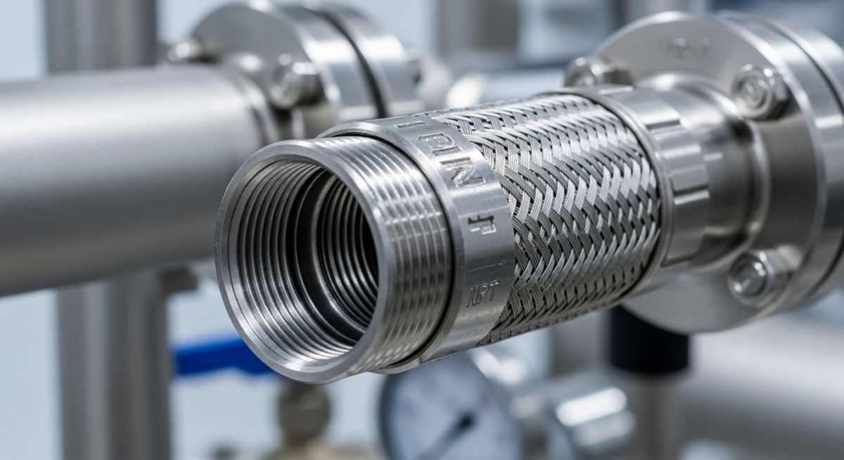
Flexible Metal Hoses: These metallic conduits are engineered to handle extreme temperatures and pressures while maintaining absolute vacuum integrity under dynamic loading conditions.
Non-metallic Flexible Hoses
While elastomeric or PTFE hoses offer excellent chemical resistance and flexibility, they fall short in severe service. Elastomers degrade rapidly under ultraviolet exposure, high temperatures, and radiation. PTFE, though chemically inert, suffers from permeation issues with low-molecular-weight gases and cannot withstand temperatures exceeding 260°C. Metallic alternatives provide a continuous, impermeable barrier that operates reliably from cryogenic zones (-200°C) up to extreme process temperatures exceeding 600°C.
Types of Metallic Flexible Hoses
Metallic hoses are broadly categorized into two distinct structural designs based on their manufacturing method and mechanical behavior:
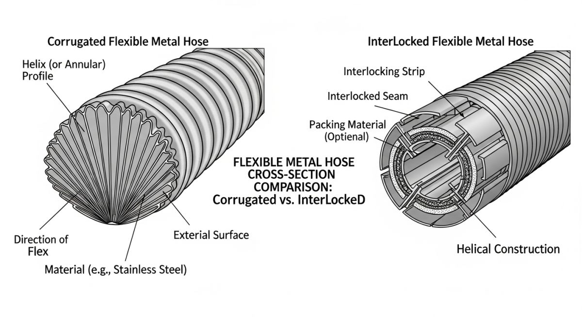
Corrugated Hose:
Formed from thin-walled tubing, corrugated hoses feature parallel (annular) or spiral (helical) ridges. Annular corrugations are the industry standard for piping systems because they do not generate torsional stresses when subjected to longitudinal expansion or contraction. To prevent the hose from elongating under internal pressure, one or more layers of external wire braiding are tightly woven over the core. This braid provides the necessary tensile strength to resist hoop and axial stresses.
Interlocked Hose:
Constructed by winding profiled metal strips over a mandrel, interlocked hoses rely on mechanically sliding joints. This design offers exceptional mechanical strength, high resistance to crushing, and excellent flexibility. However, because the joints are mechanical rather than welded, they are not pressure-tight unless fitted with specialized elastomeric packing. They are primarily utilized as protective outer casings, exhaust ducts, or bulk material transfer lines where minor leakage is acceptable.
Stress Analysis Calculations for Flexible Metal Hoses
Stress Analysis for Flexible Metal Hoses: This evaluation determines the fatigue life, spring rate, and allowable displacement limits of metallic hoses under cyclic thermal and mechanical loads in compliance with EJMA and ISO 10380.
When performing stress analysis in software like CAESAR II, a flexible hose cannot be modeled as a simple rigid pipe. It must be treated as a flexible element with specific lateral and axial stiffness values. The most critical calculation during the design phase is determining the minimum live length required to absorb lateral offset without exceeding the allowable bend radius.
Lateral Offset Formula (ISO 10380)
To calculate the required live length of a hose subjected to lateral offset in a single plane, use the following formula:
L = √(6 × Y × R + Y2)
Where:
- L = Live length of the corrugated hose (mm)
- Y = Lateral offset or dynamic movement (mm)
- R = Minimum dynamic bend radius of the hose (mm)
Let us walk through a practical field calculation. Suppose we are installing a 2-inch nominal diameter 316L stainless steel hose to absorb a lateral thermal movement of 30 mm. The manufacturer’s catalog specifies a minimum dynamic bend radius (R) of 280 mm.
Step-by-Step Calculation:
- Multiply 6 by the lateral offset and the bend radius: 6 × 30 × 280 = 50,400
- Square the lateral offset: 302 = 900
- Sum the values: 50,400 + 900 = 51,300
- Take the square root of the sum: √51,300 ≈ 226.5 mm
The minimum live length (L) required is 226.5 mm. To find the Overall Length (OAL) for ordering, you must add the length of the end fittings to this live length.
CRITICAL FIELD WARNING: Torsional Destruction
In my years on site, I have seen dozens of braided hoses fail within hours of commissioning due to torsional stress. Corrugated hoses are completely incapable of absorbing torque. A twist of only 2 to 3 degrees can reduce the hose’s pressure rating by up to 90% and cause rapid fatigue cracking along the corrugation welds. Always use a backup wrench on the hex flats when tightening threaded connections to prevent twisting.
Pipe Supporting for Optimum Hose Working
Proper pipe supporting is a fundamental requirement for the longevity of any flexible assembly. The hose must never be used to compensate for piping misalignment during installation. Pipe anchors must be positioned immediately upstream and downstream of the flexible assembly to isolate the hose from external piping loads. Additionally, guide supports should be installed to ensure that the movement of the piping is directed strictly along the active plane of the hose, preventing out-of-plane bending.
Factors for Metallic Flexible Hose Selection
To ensure a safe and reliable design, I always utilize the S.T.A.M.P.E.D. methodology during the selection process:
- Size: The nominal diameter of the piping system and the velocity of the media. High velocities may require an internal liner to prevent resonant vibration of the corrugations.
- Temperature: The operating, design, and ambient temperatures. High temperatures require de-rating of the maximum allowable working pressure.
- Application: The nature of the movement (vibration, lateral offset, angular deflection) and the frequency of cycles.
- Media: Chemical compatibility of the process fluid with the hose core, braid, and end fittings.
- Pressure: The maximum operating, test, and surge pressures. Double braiding may be required for high-pressure applications.
- End Connections: The type of fittings required (e.g., ASME B16.5 flanges, NPT threads, weld prep ends) and their materials.
- Delivery: Special testing requirements, such as helium leak testing or dye penetrant testing of the welds.
Codes and Standards for Flexible Hoses
Compliance with international standards is mandatory for safety-critical applications. The primary design code is ISO 10380, which defines the requirements for corrugated metal hoses and hose assemblies. For process piping applications, the design must align with ASME B31.3, specifically Chapter IX for high-pressure piping where applicable.
The physical properties of metals degrade as temperature increases. The table below provides the standard de-rating factors that must be applied to the maximum allowable working pressure (MAWP) of flexible metal hoses at elevated temperatures.
| Operating Temp (°C) | 304 Stainless Steel | 316L Stainless Steel | 321 Stainless Steel | Monel 400 | Hastelloy C276 |
|---|---|---|---|---|---|
| 20 | 1.00 | 1.00 | 1.00 | 1.00 | 1.00 |
| 150 | 0.86 | 0.89 | 0.92 | 0.87 | 0.93 |
| 250 | 0.74 | 0.78 | 0.84 | 0.79 | 0.86 |
| 350 | 0.66 | 0.70 | 0.77 | 0.72 | 0.80 |
| 450 | 0.59 | 0.64 | 0.71 | — | 0.75 |
| Hose Profile | Primary Material | Max Temp (°C) | Pressure Range | Design Standard | Typical Application |
|---|---|---|---|---|---|
| Annular Corrugated | 316L SS / Hastelloy | 600+ | Vacuum to 250 Bar | ISO 10380 | High-pressure steam, chemical transfer |
| Helical Corrugated | 321 SS | 550 | Vacuum to 150 Bar | ISO 10380 | Cryogenic liquid transfer, gas lines |
| Interlocked (Packed) | Galvanized Steel / 304 SS | 250 | Low Pressure (< 5 Bar) | Manufacturer Std | Engine exhaust, bulk dry powder transfer |
Site Installation Checklist for Flexible Hoses
Hose Installation Verification: This quality control protocol ensures that flexible metal assemblies are installed without torsional strain, over-bending, or misalignment prior to system pressurization.
Before signing off on a piping system commissioning sheet, I require my field inspectors to verify every flexible hose installation against this strict checklist. Skipping even one of these checks can lead to premature fatigue failure or catastrophic rupture.
Pre-Commissioning Field Checks
-
Verify Alignment: Ensure the hose is installed completely straight without any initial lateral offset or axial compression that exceeds the design limits.
-
Check for Torsion (Twisting): Confirm that the layline of the hose is perfectly straight. Any spiral pattern in the layline indicates the hose was twisted during installation.
-
Inspect Braid Integrity: Check the external wire braiding for broken strands, kinks, or weld spatter. Damaged braiding drastically reduces the pressure rating.
-
Confirm Support Locations: Verify that pipe anchors and guides are installed according to the stress analysis isometric drawing to isolate the hose from external piping loads.
-
Validate Bend Radius: Measure the actual bend radius of the hose in its operating position to ensure it is larger than the manufacturer’s specified minimum dynamic bend radius.
Field Case Study: Real-World Application
The Problem: Reciprocating Compressor Vibration Failure
At a petrochemical refinery in 2018, a reciprocating hydrogen compressor discharge line experienced severe high-frequency vibration. The original design utilized rigid carbon steel piping with standard expansion loops. Within three weeks of operation, the weld joint at the first discharge elbow developed fatigue cracks, leading to a hazardous gas leak and an unscheduled plant shutdown. The rigid piping was simply unable to absorb the continuous, high-frequency mechanical pulses generated by the compressor pistons.
The Solution & Outcome: Engineered Flexible Assembly
I was brought in to redesign the piping interface. We replaced the rigid elbow configuration with a double-braided, corrugated 316L stainless steel flexible hose. Using the lateral offset formula, we calculated a required live length of 450 mm to safely absorb the 15 mm of dynamic vibration amplitude. We also installed a heavy-duty anchor immediately downstream of the hose to isolate the rest of the piping system.
The result was immediate: the vibration was completely isolated within the flexible assembly, and the downstream piping remained completely static. The plant restarted safely, and during our follow-up inspection four years later, the hose showed zero signs of fatigue or wear.
Frequently Asked Engineering Questions
Why does torsional stress destroy flexible metal hoses so quickly?
What is the difference between annular and helical corrugations?
How does external wire braiding increase pressure capacity?
Can flexible metal hoses be used for high-vacuum applications?
How do temperature de-rating factors affect hose selection?
What are the primary causes of premature failure in metallic hoses?
===
Complete Course on
Piping Engineering
Check Now
Key Features
- 125+ Hours Content
- 500+ Recorded Lectures
- 20+ Years Exp.
- Lifetime Access
Coverage
- Codes & Standards
- Layouts & Design
- Material Eng.
- Stress Analysis
