
Pre-Commissioning and Commissioning Checklist for Flare Package
In my two decades of field experience, I have seen too many projects stumble at the final hurdle: the flare system. It is the ultimate safety barrier of any process plant, yet it is often treated as an afterthought during the construction phase. Commissioning a flare package is not merely about turning a valve; it is about validating the entire pressure relief chain, from the source headers to the pilot ignition and flame monitoring systems.
This guide provides a rigorous, field-tested framework for transitioning your flare package from mechanical completion to operational readiness. We will navigate the complexities of purging, leak testing, and logic validation to ensure your facility meets the highest safety benchmarks.
Key Commissioning Takeaways:
- Verification of purge gas flow rates to prevent flashback.
- Validation of pilot ignition sequences and flame detection sensors.
- Integrity testing of the flare header piping per ASME B31.3.
- Calibration of pressure control loops and emergency shutdown logic.
Technical Deep-Dive: Flare Package Commissioning
Flare Package Commissioning: A multi-stage engineering validation process ensuring that flare headers, knockout drums, and ignition systems function within the design parameters defined by API 521.
The commissioning of a flare package begins long before the first hydrocarbon enters the header. My approach focuses on the “Cold” and “Hot” commissioning phases. During the cold phase, we prioritize the mechanical integrity of the piping network. This involves pneumatic testing of the flare header to ensure that weld joints, flange connections, and support structures can withstand the thermal expansion cycles inherent in flare operations.
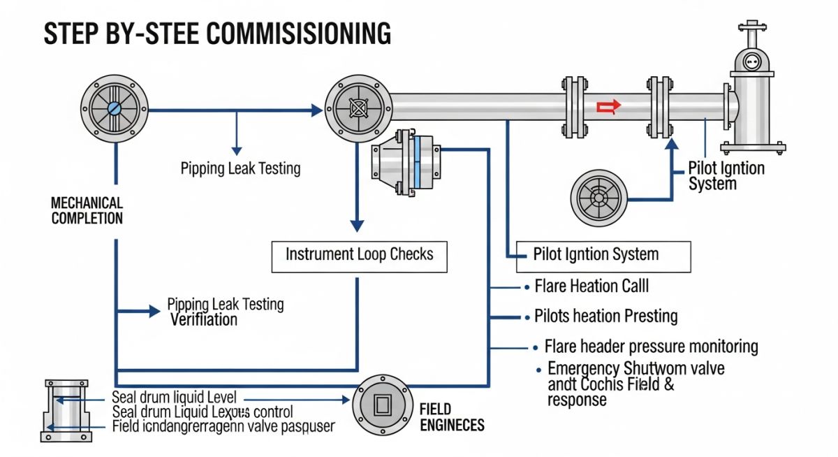
Pressure Relief and Header Integrity
The flare header must be verified for slope and drainage. Any liquid accumulation in the header can lead to severe slugging or “flame-out” conditions. I mandate a slope check of at least 1:500 toward the knockout drum. Furthermore, the ASME B31.3 code requirements for piping flexibility must be re-verified during the pre-commissioning walkdown to ensure that thermal expansion loops are not constrained by temporary construction supports.
Field Warning: Purge Gas Management
Failure to maintain the correct purge gas velocity is the leading cause of internal header corrosion and potential flashback. Ensure that the purge gas flow rate is calculated based on the molecular weight of the process gas and the cross-sectional area of the flare tip. Always verify the oxygen concentration at the flare tip using portable analyzers before introducing any process stream.
Control Logic and Safety Instrumented Systems
The final stage of commissioning involves the functional testing of the Safety Instrumented Systems (SIS). This includes the pilot flame monitoring sensors (typically infrared or ultraviolet) and the ignition control panel. We simulate a “loss of flame” signal to verify that the control system initiates the re-ignition sequence within the time limits specified in the project’s Cause and Effect matrix. Every logic gate must be tested against the design P&ID to ensure that the flare system remains in a “fail-safe” state during a power loss or instrument air failure.
Systematic Commissioning Benefits: A structured approach to flare package validation minimizes operational risk and ensures long-term compliance with environmental and safety regulations.
Advantages
- Early detection of piping stress and support binding.
- Validation of purge gas efficiency prevents internal corrosion.
- Ensures compliance with API 521 safety standards.
- Reduces the risk of unplanned shutdowns during startup.
- Optimizes pilot fuel consumption through precise calibration.
Disadvantages
- High initial labor cost for comprehensive testing.
- Requires specialized equipment for gas analysis and leak detection.
- Extended project schedule due to rigorous logic verification.
- Potential for minor delays if piping slope issues are identified.
- Complexity in coordinating multi-disciplinary teams (I&E, Piping, Process).
Industrial Flare Deployment: The application of rigorous commissioning protocols is essential across diverse sectors to maintain environmental compliance and operational safety.
Refinery Hydrocarbon Processing
In large-scale refineries, the flare system manages high-pressure relief from distillation columns and hydrocrackers. Commissioning here focuses on the capacity of the knockout drum to handle liquid carryover during emergency depressurization events.
Natural Gas Liquefaction (LNG) Plants
LNG facilities require cryogenic-rated materials for flare headers to prevent brittle fracture. Commissioning involves verifying the integrity of these low-temperature piping systems and ensuring that the flare tip can handle the high-velocity discharge of methane-rich streams.
Petrochemical Feedstock Decarbonization
Modern petrochemical plants utilize flare gas recovery units (FGRU) to minimize emissions. Commissioning these units requires precise integration with the main flare header to ensure that the recovery compressor does not interfere with the emergency relief capacity of the flare.
Successful commissioning of a flare package requires rigorous adherence to specific operational thresholds. These parameters are not merely suggestions but are critical safety boundaries defined by API 521 and ASME B31.3. During the pre-commissioning phase, engineers must verify that every instrument, valve, and piping component is calibrated to handle the design pressure and temperature fluctuations inherent in emergency relief scenarios.
The following table outlines the essential technical parameters that must be validated during the final walk-down and functional testing. Pay close attention to the pilot ignition system and the seal drum liquid levels, as these are the most frequent points of failure during initial startup sequences. Ensure that all pressure gauges are within their certified calibration window and that the flare header slope is verified to prevent liquid accumulation.
| Parameter | Standard Reference | Acceptance Criteria |
|---|---|---|
| Flare Header Slope | ASME B31.3 | Minimum 1:500 toward knockout drum |
| Seal Drum Level | API 521 | Within +/- 5mm of design setpoint |
| Pilot Ignition Time | NFPA 85 | Less than 10 seconds per attempt |
| Purge Gas Flow | API 537 | Maintain positive pressure at tip |
The complexity of a modern flare package necessitates a clear mapping of mechanical, electrical, and control entities. This matrix serves as a cross-reference tool for commissioning engineers to ensure that the physical installation aligns with the Process and Instrumentation Diagrams (P&IDs) and the original design intent. By categorizing these entities, we reduce the risk of oversight during the transition from construction to operational status.
Each entity listed below is tied to a specific safety function. For instance, the Flame Arrestor is critical for preventing flashback into the header, while the Knockout Drum (KOD) is the primary defense against liquid carryover to the flare tip. Verify that all tag numbers match the site installation and that the associated logic in the Distributed Control System (DCS) is fully functional before introducing any process gas.
Before initiating the flare system, a comprehensive site verification is mandatory. This checklist focuses on the physical integrity of the piping, the functionality of the control loops, and the readiness of the safety instrumentation systems. I have found that most commissioning delays stem from minor oversights in the field, such as unremoved blinds or improperly set pressure switches.
- Piping Integrity: Verify all flange bolts are torqued to ASME PCC-1 specifications and all temporary construction blinds have been removed.
- Instrument Calibration: Confirm all pressure transmitters and level switches are calibrated and loop-checked to the DCS.
- Seal Drum Readiness: Ensure the seal drum is filled with the correct fluid type and level as per the process data sheet.
- Ignition System: Perform a cold-start test of the pilot ignition system to ensure spark generation and flame detection.
- Purge Gas System: Verify the nitrogen purge flow rate is sufficient to maintain a positive pressure at the flare tip.
- Safety Interlocks: Validate that all emergency shutdown (ESD) valves close within the required stroke time.
Always document the results of each check with the date and the name of the verifying engineer. If any item fails, the system must remain in a non-operational state until corrective actions are verified and signed off by the lead process engineer.
Problem: Unexpected Liquid Carryover During Initial Startup
- The knockout drum level transmitter provided false readings due to improper installation.
- Condensate accumulated in the flare header due to a lack of proper slope in a low-lying section.
- The high-level alarm failed to trigger the ESD valve, leading to liquid reaching the flare tip.
- The flare tip experienced thermal shock, causing structural damage to the pilot assembly.
Outcome: Successful Remediation and Operational Stability
- Re-calibrated the level transmitter and verified the installation against the P&ID.
- Installed a high-point drain to remove accumulated condensate from the header.
- Updated the logic in the DCS to ensure a hard-wired interlock for the ESD valve.
- Replaced the damaged pilot assembly and performed a full-load test with nitrogen.
My recommendation for future projects is to perform a thorough “dead-leg” and “low-point” audit during the pre-commissioning phase. Never assume that the piping slope is correct based on the isometric drawings alone; verify it with a laser level on-site.
Frequently Asked Engineering Questions
What is the primary purpose of the seal drum?
- Preventing flashback from the flare tip into the upstream process piping.
- Maintaining a constant back-pressure to ensure stable flow conditions.
- Providing a liquid seal that allows gas to pass to the flare while blocking air ingress.
Refer to API 521 for detailed design requirements regarding seal drum sizing and liquid depth calculations.
How do I verify the flare header slope?
- Use a calibrated laser level to measure the elevation at every support point.
- Ensure the slope is at least 1:500 toward the knockout drum as per ASME B31.3.
- Check for any sagging in the pipe spans that might create liquid traps.
If a section fails to meet the slope requirement, it must be corrected by adjusting the pipe supports before the system is commissioned.
Why is nitrogen purging essential for flare systems?
- It displaces oxygen, ensuring the gas mixture remains outside the flammability limits.
- It maintains a positive pressure at the flare tip, preventing air from entering the system during low-flow conditions.
- It is a requirement under API 537 for safe flare operation.
Always monitor the nitrogen flow rate continuously to ensure it remains above the minimum design threshold.
What are the risks of improper flame arrestor installation?
- Flashback can travel through the header, causing an explosion in the upstream process units.
- The arrestor element can become clogged, leading to excessive pressure drop and potential header rupture.
- Incorrect orientation or flow direction will render the device ineffective during a flame propagation event.
Always verify the manufacturer’s installation manual and ensure the device is certified to ISO 16852 standards.
How often should pilot ignition systems be tested?
- Initial testing should confirm the spark energy and flame detection sensitivity.
- Operational testing should be performed according to the site’s safety management system, typically every 6 to 12 months.
- Any maintenance on the pilot assembly requires a full functional test before returning the flare to service.
Refer to NFPA 85 for guidance on burner management and ignition system safety.
What is the role of the knockout drum?
- It removes liquid droplets and slugs from the relief gas stream.
- It prevents liquid carryover to the flare tip, which could cause burning liquid to fall to the ground.
- It provides a collection point for condensate that can be pumped back to the process or to a waste treatment facility.
Proper sizing and level control are essential for the drum to function correctly under peak relief conditions as defined by API 521.
📚 Recommended Resources: Flare Package Commissioning
Read these Guides


Complete Course on
Piping Engineering
Check Now
Key Features
- 125+ Hours Content
- 500+ Recorded Lectures
- 20+ Years Exp.
- Lifetime Access
Coverage
- Codes & Standards
- Layouts & Design
- Material Eng.
- Stress Analysis
