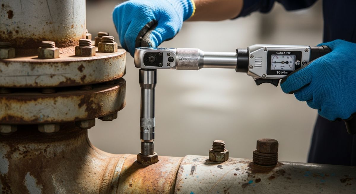
Mastering Flange Bolt Torque Calculation for Leak-Free Piping Systems
In my 20 years of piping engineering, I have seen countless flange joints fail during hydrotests or, worse, during plant startup. Almost every single one of those failures traced back to a common culprit: improper bolt tightening. Many field technicians still rely on “feel” or outdated impact wrenches without understanding the physics of joint relaxation.
To achieve a leak-free joint, we must treat the flange, bolt, and gasket as a single, dynamic spring system. This guide breaks down the exact engineering steps to perform a precise torque calculation and provides a standardized reference chart to keep your field operations safe, compliant, and highly efficient.
Key Engineering Takeaways
- Understand how the nut factor (friction coefficient) directly dictates up to 90% of your torque loss.
- Learn the step-by-step formula to calculate target torque based on gasket seating stress.
- Access a verified ASME B16.5 torque reference table for ASTM A193 B7 bolting.
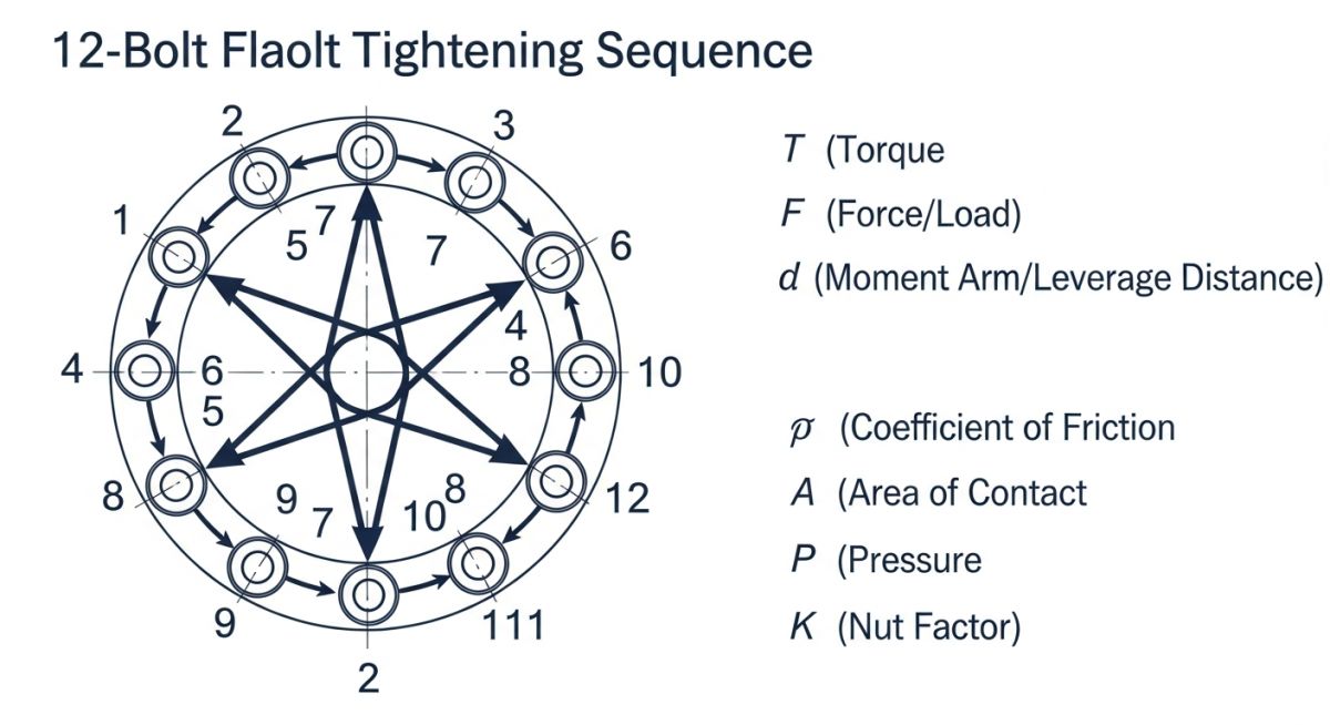
- Implement the ASME PCC-1 legacy star-pattern tightening sequence to prevent flange rotation.
How to Perform Flange Bolt Torque Calculation
To calculate the required torque, we must first determine the target bolt preload force. This force must be high enough to compress the gasket into the flange serrations, yet low enough to avoid yielding the bolt or crushing the gasket. The calculation relies on the fundamental torque-tension relationship defined by the standard formula:
Where:
– T = Target Torque (foot-pounds, ft-lbs)
– K = Nut Factor (dimensionless friction coefficient)
– D = Nominal Bolt Diameter (inches)
– F = Target Bolt Preload Force (pounds, lbs)
Step 1: Determine the Target Bolt Preload Force (F)
The target preload force is derived from the required gasket stress. Under ASME PCC-1 guidelines, the gasket must experience a minimum seating stress (S_g) to seal the micro-imperfections on the flange face. The total force required is:
Where:
– S_g = Target Gasket Stress (psi)
– A_g = Effective Gasket Contact Area (square inches)
Once the total force is known, we divide it by the number of bolts (N) to find the force per bolt (F):
Step 2: Account for the Nut Factor (K)
The nut factor, K, is a critical variable. It is not simply the coefficient of friction; it is an empirical value that accounts for thread friction, nut-face friction, and thread geometry. In my experience, failing to use the correct lubricant is the leading cause of joint failure.
- Dry Steel Bolts: K = 0.20 (highly unpredictable, prone to galling)
- Well-Lubricated Bolts (Nickel/Copper Anti-Seize): K = 0.15 (standard industrial target)
- PTFE-Coated Bolts: K = 0.12 (highly lubricious, requires lower torque to achieve the same preload)
Never apply torque values calculated for lubricated bolts to dry or rusty bolts. If you apply a torque meant for K = 0.15 to a dry bolt with K = 0.22, you will achieve only 68% of the required preload force. This will inevitably lead to gasket bypass and joint leakage during pressure testing.
Step 3: Tightening Sequence and Load Control
Applying the calculated torque all at once will warp the flange and pinch the gasket. I always enforce a multi-stage tightening sequence using the star pattern shown above. This ensures the gasket compresses evenly across its entire surface area.
The table below provides target torque values for standard ASME B16.5 flanges. These values are calculated using ASTM A193 Grade B7 bolts (yield strength of 105,000 psi) with a target bolt stress of 50,000 psi (approximately 48% of yield) and a nut factor of K = 0.15 (well-lubricated).
| NPS (Inches) | Flange Class | Bolt Qty | Bolt Dia (Inches) | Target Preload (Lbs) | Target Torque (Ft-Lbs) |
|---|---|---|---|---|---|
| 2″ | Class 150 | 4 | 5/8″ | 11,300 | 88 |
| 2″ | Class 300 | 8 | 5/8″ | 11,300 | 88 |
| 4″ | Class 150 | 8 | 5/8″ | 11,300 | 88 |
| 4″ | Class 300 | 8 | 3/4″ | 16,700 | 157 |
| 6″ | Class 150 | 8 | 3/4″ | 16,700 | 157 |
| 6″ | Class 300 | 12 | 3/4″ | 16,700 | 157 |
| 8″ | Class 150 | 8 | 3/4″ | 16,700 | 157 |
| 8″ | Class 300 | 12 | 7/8″ | 23,100 | 253 |
This matrix maps the core physical parameters, standards, and engineering entities required to execute a compliant flange assembly.
| Entity / Parameter | Standard Reference | Physical Scope | Engineering Impact |
|---|---|---|---|
| ASTM A193 B7 | ASTM A193 | Chromium-molybdenum alloy steel bolting | High-tensile strength limits; dictates maximum allowable preload stress. |
| ASME PCC-1 | ASME PCC-1 Guidelines | Pressure boundary flanged joint assembly | Defines tightening patterns, target gasket stress, and technician qualification. |
| Nut Factor (K) | ASME PCC-1 Appendix H | Frictional coefficient of the thread and nut face | Directly scales torque requirements; highly dependent on lubricant selection. |
| Gasket Seating Stress | ASME Section VIII Div 1 | Minimum compressive stress on gasket area | Ensures the gasket material flows into flange serrations to block leak paths. |
Why Flange Bolt Torque Calculation Prevents Failures
Even the most precise calculations are useless if the field execution is flawed. I have established this checklist on dozens of construction sites to guarantee that the calculated torque translates directly to the required bolt stretch.
Site Verification Checklist
-
Flange Alignment Verification: Ensure flange faces are parallel within 0.010 inches per inch of flange diameter, and bolt holes align within 1/8 inch. Never use bolt torque to pull misaligned piping together.
-
Bolt and Nut Inspection: Verify bolts are free of rust, burrs, and thread damage. Nuts must run freely by hand along the entire length of the bolt thread.
-
Lubricant Application: Apply a uniform, thin coat of approved anti-seize lubricant to the bolt threads and the nut-bearing face. Do not lubricate the gasket face.
-
Multi-Stage Torque Execution: Tighten bolts in four distinct passes using a calibrated torque wrench:
- Pass 1: Tighten to 30% of target torque using the star pattern.
- Pass 2: Tighten to 60% of target torque using the star pattern.
- Pass 3: Tighten to 100% of target torque using the star pattern.
- Pass 4: Perform a final clockwise rotational pass at 100% torque to ensure uniform load.
-
Gasket Centering: Confirm the gasket is perfectly centered on the raised face. An offset gasket will restrict flow and cause a high-pressure leak path.
Field Case Study: Real-World Application
During a refinery turnaround, a 12-inch Class 300 superheated steam line (operating at 650 degrees Fahrenheit and 450 psi) repeatedly failed its hydrotest. The field crew had tightened the ASTM A193 B7 bolts using standard impact guns without torque control. The gasket, a spiral-wound type with a graphite filler, was severely crushed on one side while showing almost no compression on the opposite side. This uneven loading caused flange rotation and a continuous leak path.
I stepped in and halted the impact-tightening practice. We calculated the exact target torque using a target gasket stress of 10,000 psi, which yielded a target bolt torque of 253 ft-lbs (assuming K = 0.15 with nickel anti-seize). We replaced the damaged gasket, cleaned the flange faces, and executed the ASME PCC-1 star pattern in four controlled stages. During the subsequent hydrotest and hot-startup, the joint remained completely dry and leak-free.
This case proves that relying on field intuition instead of calculated engineering values is a recipe for failure. By implementing a standardized torque calculation and tightening protocol, we saved the project three days of unscheduled downtime and eliminated a severe safety hazard.
Frequently Asked Engineering Questions
What is the most common cause of flange bolt torque loss after installation?
How does the nut factor (K) change if I use PTFE-coated bolts instead of standard alloy steel?
Can I reuse ASTM A193 B7 bolts after they have been torqued?
What is the difference between torque control and tension control?
Why is a final rotational pass required after the star pattern is complete?
How do operating temperature variations affect the calculated torque?
Complete Course on
Piping Engineering
Check Now
Key Features
- 125+ Hours Content
- 500+ Recorded Lectures
- 20+ Years Exp.
- Lifetime Access
Coverage
- Codes & Standards
- Layouts & Design
- Material Eng.
- Stress Analysis