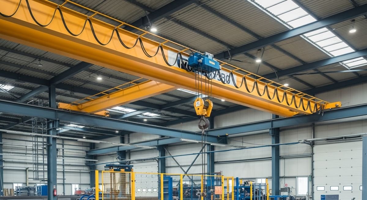
Introduction to EOT Cranes and Hoists: Design and Safety
In my two decades of field experience, I have observed that the reliability of an industrial facility often hinges on the precision of its overhead lifting systems. An EOT crane is not merely a piece of equipment; it is a complex integration of structural steel, electrical drive systems, and mechanical braking mechanisms that must operate in perfect harmony.
Whether you are designing a new bay or retrofitting an existing workshop, understanding the nuances of bridge girders, end trucks, and hoist duty cycles is non-negotiable. We must move beyond basic capacity ratings and look at the dynamic forces, fatigue life, and safety interlocks that define a high-performance lifting environment.
Key Takeaways for Engineers:
- Mastering ASME B30.2 and CMAA 70 classification requirements.
- Calculating dynamic load factors for high-speed trolley movement.
- Implementing redundant braking systems for critical load handling.
- Ensuring structural deflection limits meet serviceability criteria.
Technical Design Parameters for EOT Cranes and Hoists
EOT Crane Structural Integrity: The design of overhead systems requires rigorous analysis of static and dynamic loads, ensuring compliance with ASME B30.2 and CMAA Specification 70 for bridge and trolley performance.
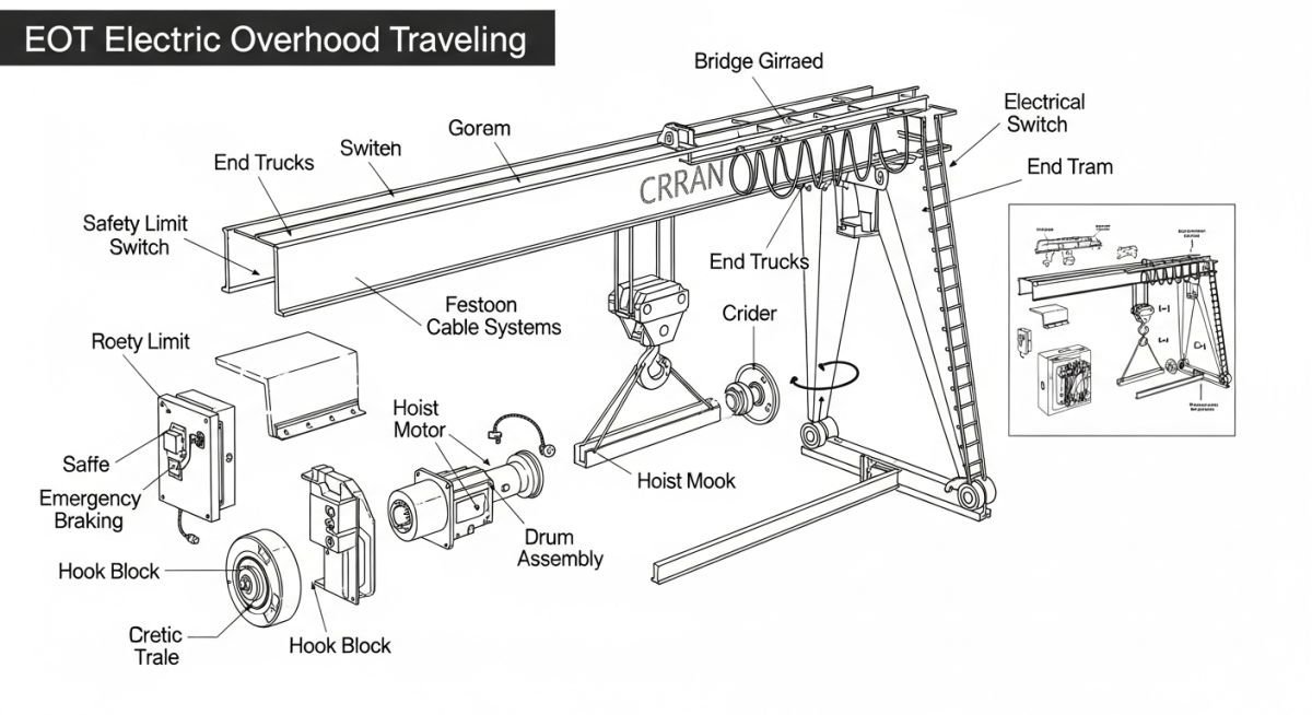
When I approach the design of an EOT crane, the first step is defining the service class. The CMAA classifies cranes from A (Standby) to F (Continuous Severe Service). This classification dictates the design life, which is measured in load cycles. For a Class F crane, we are looking at over 2 million load cycles, requiring fatigue analysis of every welded connection on the bridge girder.
The bridge girder design is governed by deflection limits. Typically, for a standard hook-type crane, the vertical deflection under the rated load is limited to 1/888 of the span. However, if the crane supports a precision hoist or automated positioning system, I often specify a tighter limit of 1/1000 to prevent load sway and ensure repeatability.
Critical Design Limitation:
Never ignore the impact of lateral forces. When the trolley accelerates or decelerates, it induces a lateral force on the bridge girder equal to 20% of the combined weight of the trolley and the lifted load. This force must be accounted for in the lateral bending moment calculation of the girder flange.
Load calculations must include the dead load of the bridge, the trolley, and the hoist, plus the live load (the rated capacity). We then apply a dynamic allowance factor. For standard electric hoists, this is typically 15% to 25% of the rated load to account for the impact of sudden starts and stops. If the hoist is variable frequency drive (VFD) controlled, we can sometimes justify a lower dynamic factor, but this requires a detailed analysis of the acceleration ramp-up time.
The end trucks must be designed to distribute the wheel loads evenly across the runway rails. I always verify the wheel bearing life using the L10 life calculation method. If the crane is operating in a high-temperature environment, such as a foundry, the bearing grease and seal materials must be upgraded to high-temperature synthetic variants to prevent premature failure.
Finally, the electrical system integration is where most field issues arise. The power supply to the hoist is usually via a festoon system or a conductor bar. I recommend conductor bars for long runways to minimize maintenance, but they must be properly shielded if the environment is dusty or corrosive. Always ensure the control voltage is 120V or lower to enhance operator safety during pendant or radio remote control operations.
System Performance Evaluation: Analyzing the operational benefits and inherent limitations of EOT crane installations is vital for selecting the correct material handling solution for specific industrial environments.
Advantages
- Maximum floor space utilization by operating in the overhead plane.
- High precision load positioning through VFD-controlled hoist motors.
- Superior durability in harsh environments with proper IP-rated enclosures.
- Reduced maintenance costs compared to mobile cranes or forklifts.
- Enhanced safety through integrated limit switches and overload protection.
Disadvantages
- High initial capital expenditure for runway steel and installation.
- Permanent installation limits the crane to a fixed bay area.
- Requires periodic structural inspection of runway beams and welds.
- Complex electrical integration for automated or multi-crane systems.
- Significant downtime required for major component overhauls or upgrades.
Industrial Lifting Deployment: EOT cranes are engineered for diverse sectors, providing critical support for heavy manufacturing, power generation, and logistics operations where reliability is paramount.
Heavy Machinery Manufacturing
In assembly bays for turbines or large engines, EOT cranes provide the precise, multi-axis movement required for component alignment. These systems often utilize dual-hoist configurations to allow for the rotation of large, unbalanced loads during the assembly process.
Steel Mill Material Handling
Operating in extreme heat and high-particulate environments, these cranes are built with specialized heat shielding and high-temperature electrical components. They are essential for moving molten metal ladles and heavy scrap, requiring the highest CMAA service classifications.
Power Plant Maintenance
During turbine outages, EOT cranes are used to lift heavy casing components and rotors with extreme care to avoid damage to precision-machined surfaces. The use of creep-speed controls is standard here to ensure millimeter-level accuracy during the final seating of components.
Selecting the appropriate crane classification is the most critical step in ensuring the longevity and safety of your material handling infrastructure. These classifications, defined by CMAA and ASME B30.2, dictate the structural design requirements, motor sizing, and component fatigue life expectations for the entire system.
The following table outlines the standard service classes, ranging from Class A (Standby Service) to Class F (Continuous Severe Service). Engineers must evaluate the average load intensity and the number of load cycles per hour to determine the correct classification. Failure to match the crane duty cycle to the actual operational demand often leads to premature gearbox failure, motor overheating, and accelerated wear on the bridge and trolley wheels.
| Service Class | Typical Application | Load Intensity | Design Life (Cycles) |
|---|---|---|---|
| Class A (Standby) | Powerhouses, Public Utilities | Light/Infrequent | 20,000 – 100,000 |
| Class C (Moderate) | Machine Shops, Warehouses | Moderate | 200,000 – 500,000 |
| Class E (Severe) | Steel Mills, Scrap Yards | Heavy/Constant | 1,000,000 – 2,000,000 |
Always verify that your structural support beams are rated for the specific crane class selected, as higher duty cycles impose significantly higher dynamic impact loads on the runway rails and building columns.
The engineering of EOT cranes involves a complex interplay between mechanical, electrical, and structural disciplines. This matrix serves as a reference for the primary entities and standards that govern the design, installation, and inspection of overhead lifting systems in industrial environments.
By mapping these components to their respective regulatory bodies, engineers can ensure that every aspect of the crane—from the hoist motor to the runway conductor system—complies with international safety protocols. This matrix is intended for use during the preliminary design phase to identify potential integration conflicts between mechanical lifting capacity and structural building limitations.
| Entity/Component | Primary Standard | Key Parameter |
|---|---|---|
| Bridge Girder | ASME B30.2 | Deflection (L/800) |
| Hoist Mechanism | HMI 100 | Duty Cycle/FEM Class |
| Runway Rails | AISC Design Guide 7 | Alignment/Tolerance |
Note that while these standards provide the baseline, local jurisdictional requirements or specific site conditions may necessitate more stringent design factors, particularly in seismic zones or high-temperature process areas.
Before commissioning any EOT crane system, a comprehensive site verification is mandatory to prevent structural failure and operational hazards. This checklist focuses on the critical interface points between the crane, the runway, and the building structure, ensuring compliance with ASME B30.2 requirements.
- Runway Alignment: Verify that the span between rails is within the tolerance specified by the manufacturer, typically within 1/4 inch over the entire length.
- End Stop Integrity: Ensure all runway end stops are securely bolted and capable of absorbing the kinetic energy of the crane at full rated speed.
- Electrical Grounding: Confirm that the crane bridge and trolley are effectively bonded to the building grounding grid to prevent stray current corrosion.
- Clearance Verification: Check for a minimum of 2 inches of overhead clearance and 3 inches of side clearance from any building obstruction.
- Load Testing: Perform a static load test at 125% of the rated capacity to verify structural deflection and brake holding capability.
Document every inspection result in the site logbook. If any parameter falls outside the acceptable range, the crane must be locked out and tagged out until corrective measures are verified by a qualified engineer. Regular audits of these items are essential for maintaining the safety certification of the lifting equipment throughout its operational life.
Problem: Excessive Wheel Flange Wear in a Heavy-Duty Steel Mill
- The crane exhibited severe lateral vibration during bridge travel, leading to rapid degradation of the wheel flanges.
- Initial inspection revealed that the runway rails were misaligned by 0.75 inches over a 50-foot span.
- The building columns showed signs of thermal expansion stress, which shifted the rail centers over time.
- The crane was operating at 110% of its rated duty cycle, causing premature fatigue in the drive motor couplings.
Outcome: Successful Realignment and Operational Optimization
- The runway rails were re-leveled and re-aligned using laser-guided surveying equipment to meet strict tolerances.
- Installed floating-type wheel assemblies to accommodate minor structural deflections without inducing flange stress.
- Implemented a variable frequency drive (VFD) upgrade to reduce the dynamic impact loads during acceleration and deceleration.
- Established a quarterly laser-alignment audit schedule to monitor structural shifts before they impact crane performance.
My recommendation for similar industrial environments is to prioritize structural stability during the initial design phase. If the building structure is prone to thermal movement, always specify crane components that allow for lateral float to prevent the catastrophic failure of the bridge drive system.
Frequently Asked Engineering Questions
What is the primary difference between CMAA and ASME standards?
The primary distinction lies in their scope and focus regarding industrial lifting equipment:
- ASME B30.2 serves as the American National Standard for safety, focusing on construction, installation, operation, and maintenance requirements.
- CMAA (Crane Manufacturers Association of America) specifications focus on the design, structural integrity, and performance criteria for overhead cranes.
- Engineers must use ASME for safety compliance and legal liability, while CMAA is used for the technical design and procurement specifications.
How is the bridge deflection limit calculated?
Bridge deflection is a critical structural parameter defined by the span length of the girder:
- The standard limit for most EOT cranes is L/800, where L represents the span of the bridge in inches.
- This calculation ensures that the girder remains stiff enough to prevent excessive trolley drift and structural fatigue.
- For specialized applications, such as precision assembly, engineers may specify a tighter deflection limit like L/1000 to improve control.
Why is the duty cycle important for motor selection?
Motor selection is directly tied to the thermal capacity and operational frequency of the crane:
- High duty cycles require motors with higher insulation classes to handle the heat generated by frequent starts and stops.
- Under-specifying the duty cycle leads to rapid insulation breakdown and motor burnout.
- Always calculate the equivalent full-load hours per day to ensure the motor is rated for the actual operational intensity.
What are the requirements for runway rail alignment?
Runway alignment is essential for preventing wheel binding and structural wear:
- Rails must be parallel within the tolerances defined by the crane manufacturer and AISC guidelines.
- Vertical alignment is equally important to prevent the crane from “crabbing” or skewing during travel.
- Regular laser surveys are recommended to detect structural settling or column movement before it impacts the crane’s operation.
How do I perform a static load test?
Static load testing is a mandatory procedure for verifying structural integrity:
- Apply a test load equal to 125% of the rated capacity, as specified by ASME B30.2.
- The load should be lifted and held for a sufficient duration to observe any permanent deformation or brake slippage.
- All test results must be recorded and signed by a qualified inspector to maintain the crane’s safety certification.
What is the role of a VFD in crane control?
Variable Frequency Drives (VFDs) have revolutionized modern crane control systems:
- They provide smooth acceleration and deceleration, significantly reducing the dynamic impact loads on the crane structure.
- VFDs allow for precise speed control, which is essential for delicate lifting operations or positioning heavy loads.
- By minimizing mechanical stress, VFDs extend the service life of gearboxes, couplings, and motor components.
📚 Recommended Resources: Cranes and Hoists
Complete Course on
Piping Engineering
Check Now
Key Features
- 125+ Hours Content
- 500+ Recorded Lectures
- 20+ Years Exp.
- Lifetime Access
Coverage
- Codes & Standards
- Layouts & Design
- Material Eng.
- Stress Analysis
