Why Dynamic Analysis of Piping Systems Saves Industrial Plants
I still remember the cold sweat of standing next to a 12-inch reciprocating compressor discharge line in a Texas refinery back in 2008. The pipe was vibrating so violently that the pressure gauges were a complete blur. Within forty-eight hours, a small-bore bypass line sheared clean off at the weld, releasing high-pressure hydrocarbon gas. That incident taught me a permanent lesson: static analysis is only half the battle. When fluids pulse, valves slam, or the earth shakes, you need a rigorous dynamic assessment to keep your plant in one piece.
In my experience, many design offices treat dynamic analysis as an afterthought or a luxury. They rely on static approximations, hoping that generous safety factors will cover the gaps. But dynamic forces do not care about static safety factors. They exploit mechanical resonance, high-cycle fatigue, and structural weak points with surgical precision. This guide breaks down the exact engineering principles, calculations, and field-proven mitigation strategies required to master piping dynamics.
Key Engineering Takeaways
- Understand the critical transition from static equilibrium to time-dependent dynamic response.
- Identify the primary excitation sources: mechanical, fluid-induced, and environmental.
- Learn how to apply modal analysis to avoid destructive mechanical resonance.
- Master the design of dynamic piping supports, including snubbers, struts, and spring hangers.
- Implement code-compliant verification workflows in accordance with ASME B31.3.
How Dynamic Analysis of Piping Systems Prevents Failures
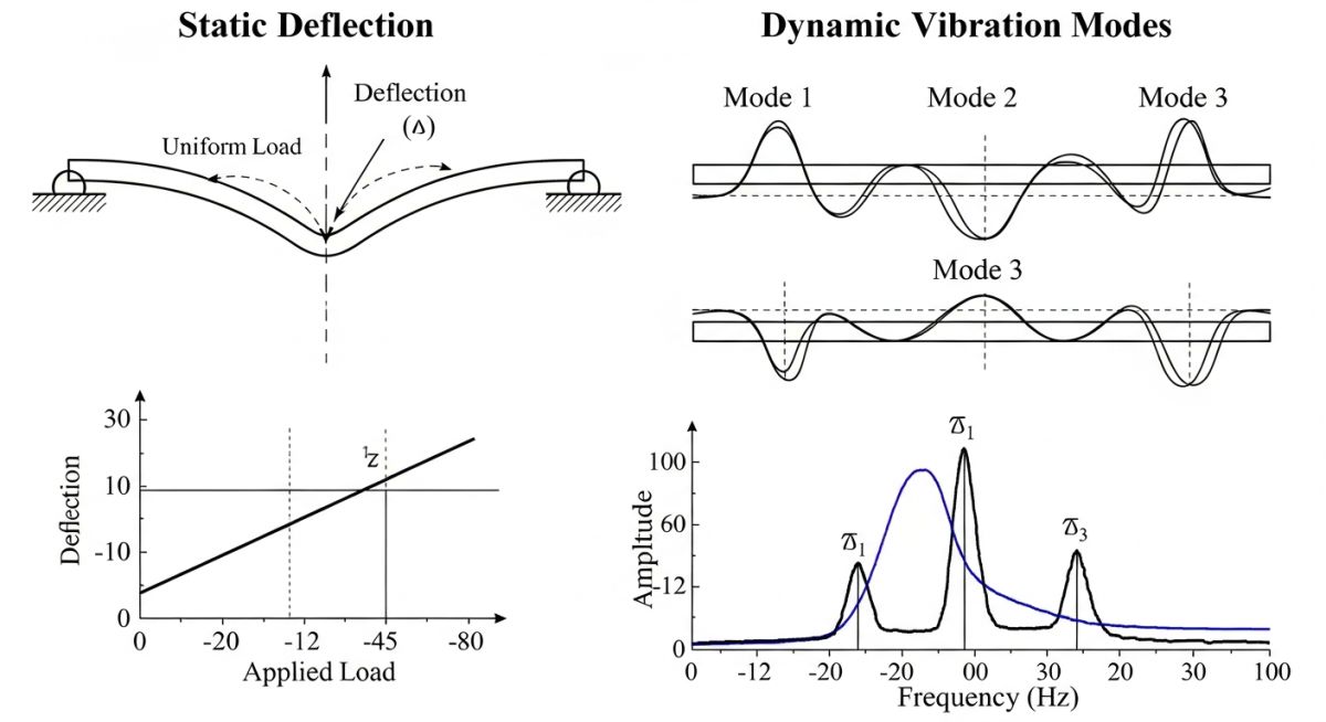
To understand why a system fails dynamically, we must look at the governing equation of motion. Unlike static analysis where force equals stiffness times displacement (F = Kx), dynamic analysis introduces mass and damping. The classic differential equation governing a multi-degree-of-freedom piping system is:
Where [M] represents the mass matrix (including pipe, fluid, insulation, and components), [C] is the damping matrix, [K] is the structural stiffness matrix, and {F(t)} is the time-varying force vector. When the frequency of the forcing function {F(t)} matches one of the natural frequencies of the system, the displacement {x(t)} increases exponentially, limited only by the damping matrix [C].
Calculating Natural Frequency
For a simplified, uniformly loaded single-span pipe, the fundamental natural frequency (fn) can be calculated using the classical beam theory equation:
Where:
• alpha = Boundary condition constant (e.g., 9.87 for simply supported, 22.4 for fixed-fixed).
• E = Modulus of elasticity of the pipe material (N/m²).
• I = Area moment of inertia of the pipe cross-section (m⁴).
• w = Total weight per unit length (kg/m), including pipe, fluid, and insulation.
• L = Span length between supports (m).
As an experienced engineer, I always look at the span length first. Because L is raised to the fourth power in the denominator, even a minor reduction in support span yields a massive increase in natural frequency. This is our primary weapon when shifting a system out of resonance zones.
In my 20 years of field audits, over 80% of dynamic piping failures occur at small-bore connections (SBCs) such as vents, drains, and pressure tap-offs. These branch lines act as cantilevered masses. When the main run pipe vibrates, the SBC experiences severe displacement amplification, leading to rapid high-cycle fatigue cracking at the run-to-branch weld. Always brace or stiffen SBCs in high-vibration services.
Modal Analysis vs. Response Spectrum Analysis
When performing computer-aided engineering, we typically utilize two primary dynamic methods:
- Modal Analysis: This is the starting point. It calculates the natural frequencies and corresponding mode shapes of the piping system without applying external loads. I use this to verify that the system’s fundamental frequency is well above the excitation frequencies of nearby rotating equipment (typically keeping a 20% safety margin).
- Response Spectrum Analysis (RSA): Primarily used for seismic design. Instead of solving the equations of motion step-by-step over time, RSA applies a pre-calculated envelope of maximum acceleration responses across a range of frequencies. It is computationally efficient and mandated by building codes like ASCE 7 and ASME B31.1.
When dynamic loads are applied rapidly, the structural response can be significantly larger than if the same load were applied statically. This relationship is quantified by the Dynamic Load Factor (DLF). The table below outlines typical DLF values used in industrial piping design based on the ratio of load duration (td) to the natural period of the system (T).
| Transient Event Type | Typical Rise Time (tr) | Theoretical Max DLF | Design Recommended DLF | Applicable Code / Standard |
|---|---|---|---|---|
| Fast Valve Closure (Water Hammer) | 5 ms to 50 ms | 2.0 | 1.2 to 1.5 (with time-history) | ASME B31.3 Appendix F |
| Safety Valve Discharge (Gas/Steam) | 10 ms to 100 ms | 2.0 | 2.0 (static equivalent) | ASME B31.1 Appendix II |
| Slug Flow Impact | 100 ms to 500 ms | 1.5 | 1.3 to 1.5 | API RP 520 / ASME B31.3 |
| Seismic Ground Motion | Variable (Cyclic) | 3.5+ (Resonant) | Based on RSA Curve | ASCE 7 Chapter 13 |
To design an effective mitigation strategy, we must map the physical phenomena to their corresponding analytical methods and hardware solutions. This matrix serves as a quick reference for engineering teams during the front-end engineering design (FEED) phase.
| Excitation Source | Primary Physical Parameter | Analytical Method | Hardware Mitigation Device | Design Standard Reference |
|---|---|---|---|---|
| Acoustic Induced Vibration (AIV) | Sound Power Level (PWL) > 155 dB | Empirical Screening / FEA Shell Modeling | Thick-walled pipe, downstream diffusers | Energy Institute Guidelines |
| Flow Induced Vibration (FIV) | Fluid Kinetic Energy (rho * v²) | Turbulence / Vortex Shedding Analysis | Stiffening supports, flow straighteners | ASME Section III Div 1 App N |
| Reciprocating Compressor Pulsation | Pressure pulsation limit (1% to 2%) | Acoustic Simulation (1D / 3D) | Pulsation dampeners, orifice plates | API Standard 618 |
| Seismic Ground Motion | Spectral Acceleration (g-force) | Response Spectrum / Equivalent Static | Seismic snubbers, sway braces | ASCE 7 / IBC Chapter 16 |
Why Dynamic Analysis of Piping Systems Requires Field Audits
No matter how sophisticated your finite element model is, it is only as good as the boundary conditions you input. In the field, supports corrode, gaps open up, and spring hangers bottom out. As a result, the real-world natural frequencies of your piping system can deviate drastically from your design model. The checklist below represents my personal field-audit protocol for verifying dynamic piping integrity.
Piping Dynamic Integrity Field Checklist
-
Verify Support Gaps: Ensure that guide and limit stop clearances do not exceed 1.5 mm (1/16 inch). Excessive gaps allow the pipe to build up kinetic energy before impacting the support, magnifying dynamic loads.
-
Inspect Spring Hangers: Confirm that all variable and constant effort spring hangers are operating within their calibrated hot/cold travel ranges. A bottomed-out spring acts as a rigid anchor, completely altering the dynamic response.
-
Check Snubber Functionality: Inspect hydraulic and mechanical snubbers for fluid leaks or mechanical binding. Snubbers must lock up during dynamic events (seismic, water hammer) but allow free thermal movement.
-
Audit Small-Bore Connections (SBCs): Identify all unsupported SBCs within 15 meters of dynamic equipment. Ensure they are braced back to the run pipe or a rigid structural member using high-stiffness gussets.
-
Validate Structural Steel Stiffness: Inspect the secondary steel supporting the piping. If the steel structure itself is flexible, it will lower the system’s overall natural frequency, rendering the piping model inaccurate.
Field Case Study: Real-World Application
The Problem: Reciprocating Compressor Manifold Cracking
At a major natural gas processing plant in Alberta, Canada, a newly commissioned three-stage reciprocating compressor experienced repeated fatigue cracking at the second-stage discharge pulsation bottle nozzle. The plant was forced to shut down three times within six weeks, costing approximately 180,000 per day in lost production.
The original design team had performed a standard static stress analysis but omitted a detailed dynamic study, assuming the pulsation bottle would absorb all energy. Field measurements revealed vibration velocities on the discharge piping exceeding 45 mm/s RMS, far above the Energy Institute allowable limit of 12 mm/s.
The Solution & Outcome: Dynamic Redesign
My team was brought in to perform an emergency dynamic assessment. We built a high-fidelity finite element model of the compressor manifold and the first 30 meters of downstream piping. Our modal analysis identified a structural natural frequency at 29.4 Hz, which was almost a perfect match for the compressor’s second-harmonic operating speed of 29.6 Hz (1480 RPM). This was a classic case of mechanical resonance.
We implemented a two-pronged mitigation strategy:
- We added two heavy-duty, high-stiffness dynamic struts (sway braces) to the pulsation bottle to shift the structural natural frequency from 29.4 Hz up to 42.1 Hz, well away from the operating envelope.
- We installed an internal orifice plate in the discharge nozzle to increase acoustic damping and reduce pressure pulsations.
As a result of these modifications, vibration velocities dropped to a safe 6.2 mm/s RMS. The plant has now operated for over four years without a single dynamic failure or unscheduled shutdown.
Frequently Asked Engineering Questions
What is the difference between static and dynamic piping analysis?
How does ASME B31.3 govern dynamic analysis?
What is Acoustic Induced Vibration (AIV) and how is it mitigated?
Why do small-bore connections fail so frequently in dynamic systems?
How do you calculate the speed of sound in a liquid-filled pipe for water hammer analysis?
When should I use Time-History Analysis instead of Response Spectrum Analysis?
Complete Course on
Piping Engineering
Check Now
Key Features
- 125+ Hours Content
- 500+ Recorded Lectures
- 20+ Years Exp.
- Lifetime Access
Coverage
- Codes & Standards
- Layouts & Design
- Material Eng.
- Stress Analysis


