How Data Centres Work: Infrastructure and Operations Overview
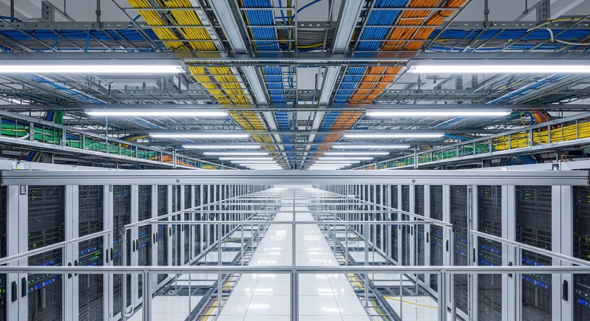
In my two decades of engineering, I have observed that the true complexity of a data centre lies not in the servers themselves, but in the invisible, high-stakes choreography of power and cooling that keeps them alive. A data centre is essentially a massive, climate-controlled machine where every kilowatt of power consumed must be balanced by an equivalent removal of heat.
Understanding how these facilities function requires a deep dive into the mechanical and electrical interdependencies that define modern uptime. From the utility substation to the rack-level power distribution unit, every component is a link in a chain where failure is not an option.
Key Takeaways
- Redundancy is the cornerstone of design, typically following N+1 or 2N configurations.
- Thermal management now prioritizes aisle containment to prevent air mixing and improve PUE.
- Power distribution must account for harmonic distortion and transient voltage surges.
- Facility operations rely on DCIM software for real-time environmental and electrical monitoring.
Data Centres Infrastructure: Technical Design and Operational Mechanics
Data Centres Infrastructure: The holistic integration of mechanical, electrical, and plumbing systems engineered to provide a stable, redundant, and secure environment for high-density IT equipment, governed by ASHRAE thermal guidelines and NFPA 75 fire protection standards.
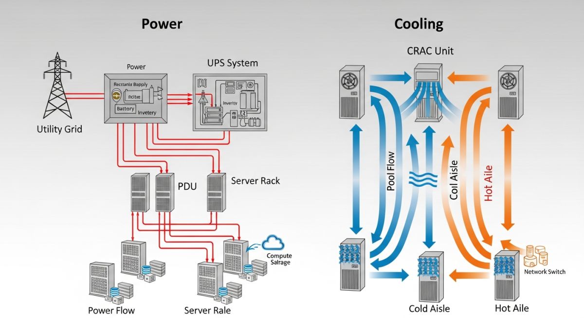
The mechanical backbone of any facility is its cooling cycle. In my experience, the transition from traditional raised-floor cooling to hot-aisle containment has been the most significant shift in efficiency. We calculate the required cooling capacity based on the total IT load, typically measured in kilowatts (kW), and apply a safety factor to account for peak processing demands.
Thermal Load Calculations
To determine the required cooling, we use the fundamental heat transfer equation: Q = m * Cp * deltaT. In a data centre, the air mass flow rate (m) must be precisely controlled to ensure that the intake temperature at the server face remains within the recommended ASHRAE envelope, typically between 18 and 27 degrees Celsius.
Electrical Distribution Architecture
Power distribution follows a strict hierarchy: Utility Feed to Medium Voltage Switchgear, then to Uninterruptible Power Supply (UPS) systems, and finally to Power Distribution Units (PDUs). The design must mitigate harmonic distortion, which is prevalent in modern switch-mode power supplies. We utilize K-rated transformers to handle the heat generated by these harmonics.
Redundancy is categorized by Tier levels. A Tier III facility requires concurrently maintainable infrastructure, meaning any component can be removed for service without impacting the IT load. This requires dual-path distribution (A and B feeds) from the UPS all the way to the rack-level PDU.
Infrastructure Operational Trade-offs: The strategic evaluation of facility design choices, balancing capital expenditure against long-term operational reliability and energy efficiency metrics like Power Usage Effectiveness (PUE).
Advantages
- High availability through N+1 or 2N redundancy.
- Scalability via modular rack and cooling designs.
- Enhanced security through physical and logical access controls.
- Optimized thermal management via aisle containment.
Disadvantages
- High initial capital expenditure for redundant systems.
- Significant energy consumption leading to high OPEX.
- Complexity in managing multi-vendor hardware integration.
- Risk of obsolescence due to rapid IT hardware cycles.
Facility Infrastructure Deployment: The practical implementation of data centre technologies across diverse sectors to support digital transformation and high-performance computing requirements.
Cloud Service Provider Facilities
These massive hyperscale facilities utilize standardized, modular infrastructure to support thousands of virtualized servers. The focus is on extreme PUE optimization and automated power management to maintain cost-efficiency at scale.
Financial Services High-Frequency Trading
Low-latency requirements dictate the use of specialized compute hardware and proximity-based infrastructure. Power systems must be ultra-stable with minimal transient response times to prevent micro-second outages during market volatility.
Healthcare Research and Genomics
Data centres supporting genomic sequencing require massive storage arrays and high-performance computing (HPC) clusters. The infrastructure must handle high-density heat loads generated by GPU-accelerated processing units.
In my two decades of managing mission-critical facilities, I have found that the primary challenge in Data Centres Infrastructure lies in balancing high-density compute loads with thermal management efficiency. The following table outlines the standard operating parameters for modern Tier III and Tier IV facilities, focusing on the relationship between power density, cooling capacity, and the resulting Power Usage Effectiveness (PUE) ratios that define operational success.
Engineers must evaluate these metrics against ASHRAE TC 9.9 guidelines to ensure that hardware longevity is not compromised by aggressive energy-saving cooling strategies. When reviewing these values, consider that the “Design Load” represents the peak theoretical capacity, while “Operational PUE” reflects the real-world efficiency of the facility under varying IT utilization rates.
| Parameter | Typical Range | Standard Reference |
|---|---|---|
| Rack Power Density | 5 kW to 30 kW | Uptime Institute |
| Supply Air Temp | 18C to 27C | ASHRAE A1-A4 |
| Target PUE | 1.1 to 1.5 | ISO/IEC 30134-2 |
| Humidity (Dew Point) | 5.5C to 15C | ASHRAE TC 9.9 |
These figures serve as the baseline for any facility audit. If your current operational PUE exceeds 1.6, I strongly recommend a comprehensive airflow management study to identify bypass air and recirculation issues that are likely inflating your cooling energy consumption.
The complexity of Data Centres Infrastructure requires a rigorous mapping of physical assets to their respective logical and electrical domains. This matrix provides a structural overview of the critical components that form the backbone of a high-availability environment, ensuring that every subsystem—from the Uninterruptible Power Supply (UPS) to the server-level Network Interface Card (NIC)—is accounted for in the facility design.
By categorizing these entities, we can better understand the interdependencies between power distribution and compute performance. For instance, the transition from traditional air cooling to liquid cooling necessitates a complete re-evaluation of the mechanical infrastructure matrix, as the heat rejection requirements shift from fan-based air movement to fluid-based heat exchange systems.
| Entity | Function | Standard |
|---|---|---|
| UPS (Static) | Power Conditioning/Backup | IEC 62040 |
| PDU | Power Distribution/Monitoring | NEMA/UL 60950 |
| CRAC/CRAH | Thermal Management | ASHRAE 90.4 |
| BMS | Facility Monitoring | BACnet/Modbus |
Utilizing this matrix during the design phase allows for the identification of potential single points of failure. Always ensure that your Building Management System (BMS) is integrated with the IT monitoring layer to provide a holistic view of the facility’s health, as isolated monitoring often leads to delayed response times during critical thermal events.
Infrastructure Integrity Verification: Before commissioning any new Data Centres Infrastructure, a rigorous site verification process is mandatory to ensure compliance with design specifications and safety standards. This checklist serves as a field guide for engineers to validate that the physical and electrical environment is ready for high-density hardware deployment.
-
Power Path Redundancy: Verify that A and B power feeds are physically separated and routed through distinct pathways to prevent common-mode failures. -
Grounding and Bonding: Confirm that all racks are bonded to the Common Bonding Network (CBN) per TIA-607-C standards to mitigate electrostatic discharge risks. -
Airflow Containment: Inspect cold aisle/hot aisle containment systems for gaps or leaks that could lead to air recirculation and reduced cooling efficiency. -
Fire Suppression Systems: Validate that VESDA (Very Early Smoke Detection Apparatus) sensors are calibrated and that gas-based suppression systems are fully charged. -
Cable Management: Ensure that data and power cables are segregated in separate trays to minimize electromagnetic interference (EMI) and maintain airflow paths.
Regular audits using this checklist are vital for maintaining the uptime guarantees expected in modern enterprise environments. I recommend performing these checks quarterly, as facility conditions—such as floor tile displacement or cable congestion—can degrade over time, leading to hidden thermal bottlenecks that are difficult to diagnose without a structured inspection routine.
Problem: Thermal Runaway in High-Density Compute Zone
A Tier III facility experienced localized overheating in a high-density rack row, leading to server throttling and intermittent hardware failures.
- Inadequate cold aisle containment allowing hot air recirculation.
- Blocked perforated floor tiles preventing sufficient airflow delivery.
- Over-provisioning of server loads beyond the cooling capacity of the local CRAC unit.
- Lack of real-time rack-level temperature monitoring.
Outcome: Optimized Thermal Management and Uptime Restoration
By implementing a comprehensive airflow management strategy, the facility successfully restored stable operating temperatures and eliminated hardware throttling.
- Reduction in average rack intake temperature by 6 degrees Celsius.
- Improvement in PUE from 1.75 to 1.42 through optimized fan speeds.
- Installation of intelligent rack-level sensors for proactive thermal alerting.
- Successful deployment of blanking panels to seal unused rack spaces.
My recommendation for similar scenarios is to prioritize the “low-hanging fruit” of airflow management—specifically blanking panels and floor tile management—before investing in expensive mechanical cooling upgrades. Often, the issue is not a lack of cooling capacity, but rather the inefficient delivery of the cooling that is already available.
Frequently Asked Engineering Questions
What is the primary difference between Tier III and Tier IV data centres?
- Tier III requires N+1 redundancy for all critical components.
- Tier IV mandates 2N or 2(N+1) redundancy for all power and cooling paths.
- Tier IV includes automated compartmentalization to prevent fire or flood from spreading.
How does PUE impact the operational cost of a data centre?
- High PUE values directly correlate to higher monthly utility bills.
- Reducing PUE by 0.1 in a 1MW facility can save thousands of dollars annually.
- Efficiency gains are often achieved through better airflow management and higher operating temperatures.
Why is humidity control critical in Data Centres Infrastructure?
- ASHRAE recommends a dew point range of 5.5C to 15C.
- Maintaining consistent humidity prevents mechanical stress on circuit boards.
- Modern sensors allow for precise control, reducing the need for energy-intensive humidification.
What is the role of a BMS in facility operations?
- BMS integration enables automated responses to thermal events.
- It provides historical data for trend analysis and capacity planning.
- Modern BMS platforms support open protocols like BACnet for multi-vendor interoperability.
How do I manage cable congestion in high-density racks?
- Use shorter patch cords to reduce excess slack.
- Implement a strict labeling system to prevent “zombie” cables.
- Regularly audit and remove abandoned cabling to improve airflow paths.
What are the benefits of liquid cooling over air cooling?
- Higher heat density support for AI and HPC workloads.
- Reduced energy consumption due to lower fan power requirements.
- Improved hardware reliability through more stable operating temperatures.
Complete Course on
Piping Engineering
Check Now
Key Features
- 125+ Hours Content
- 500+ Recorded Lectures
- 20+ Years Exp.
- Lifetime Access
Coverage
- Codes & Standards
- Layouts & Design
- Material Eng.
- Stress Analysis

📚 Recommended Resources: Data Centres Infrastructure
Read these Guides
Related posts:
![Technical infographic showing the workflow of flood risk assessment for data centres, including hydrological inputs and mitigation strategies.]()
Flood Risk Assessment for Data Centres: Engineering Design Guide
![Isometric engineering rendering of a data centre campus featuring flood protection barriers and elevated utility infrastructure for disaster resilience.]()
Flood Protection Level Selection for Mission-Critical Data Centre Infrastructure
![Cross-section diagram of a data centre foundation showing soil strata, pile foundations, and groundwater monitoring wells for geotechnical analysis.]()
Geotechnical Requirements for Data Centres: A Structural Engineering Guide
![Civil 3D interface showing a 3D site grading model with color-coded cut and fill zones for earthwork optimization.]()
Optimizing Cut and Fill Operations Using Civil 3D and GIS
![3D digital terrain model showing site grading, flood protection levels, and cut-fill zones for industrial infrastructure development.]()
Establishing FPL and Estimating Cut Fill Quantities for Site Grading
![3D engineering model showing cut and fill optimization for industrial site grading and earthwork balancing.]()
Cut and Fill Optimization: 8 Engineering Studies for Site Grading