Data Centres Explained: Engineering High-Availability Infrastructure Systems
In my two decades of experience navigating the complexities of industrial piping and facility design, few environments demand the level of precision required by modern data centres. These facilities are not merely buildings; they are highly engineered, climate-controlled ecosystems where the failure of a single valve or circuit breaker can result in catastrophic financial loss.
As we transition into an era of AI-driven computing, the thermal loads and power densities within these spaces are pushing traditional HVAC and electrical distribution systems to their absolute limits. This guide explores the fundamental engineering principles that keep these facilities operational, focusing on the rigorous standards that define modern high-availability design.
Key Engineering Takeaways:
- Understanding Tier I through Tier IV redundancy requirements.
- Mastering the integration of chilled water loops with server rack thermal loads.
- Implementing N+1 or 2N power distribution topologies for maximum reliability.
- Navigating ASHRAE TC 9.9 thermal guidelines for optimal server performance.
Core Engineering of Data Centres Infrastructure Systems
Data Centre Infrastructure Systems: The complex network of mechanical cooling, electrical power distribution, and fire suppression systems designed to maintain a stable environment for high-density IT equipment under ASHRAE environmental standards.
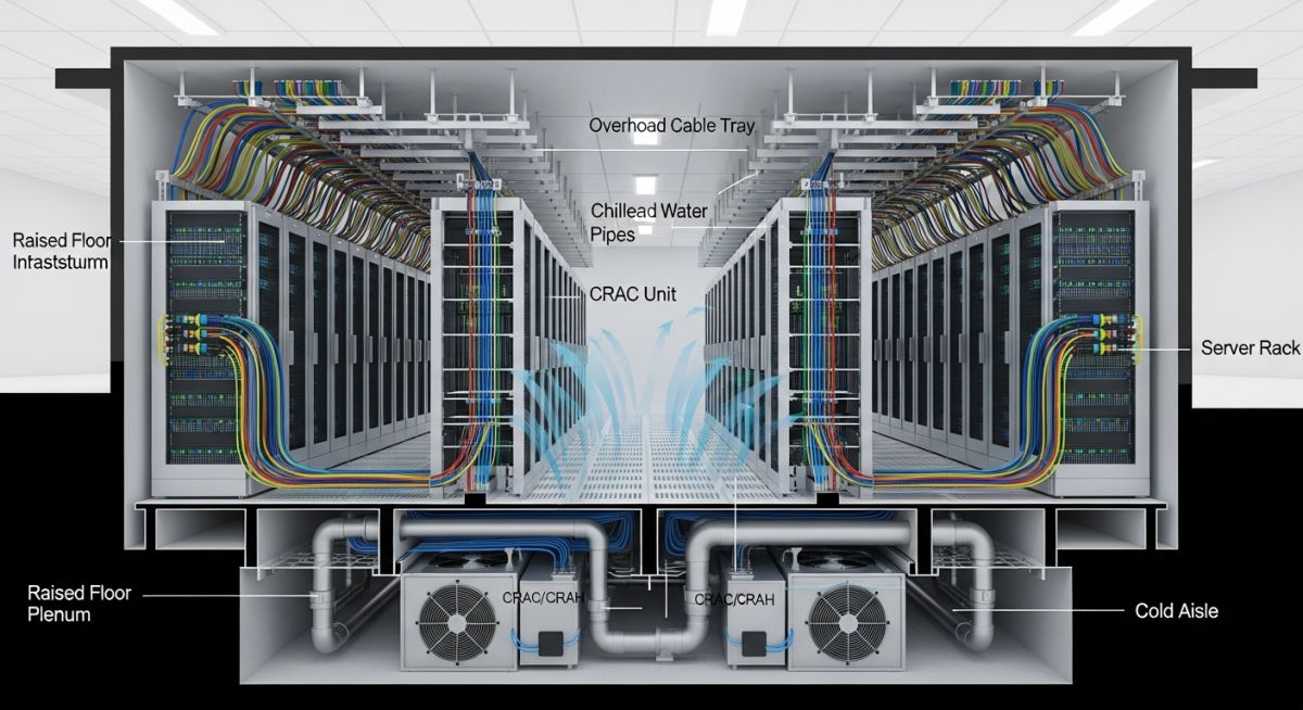
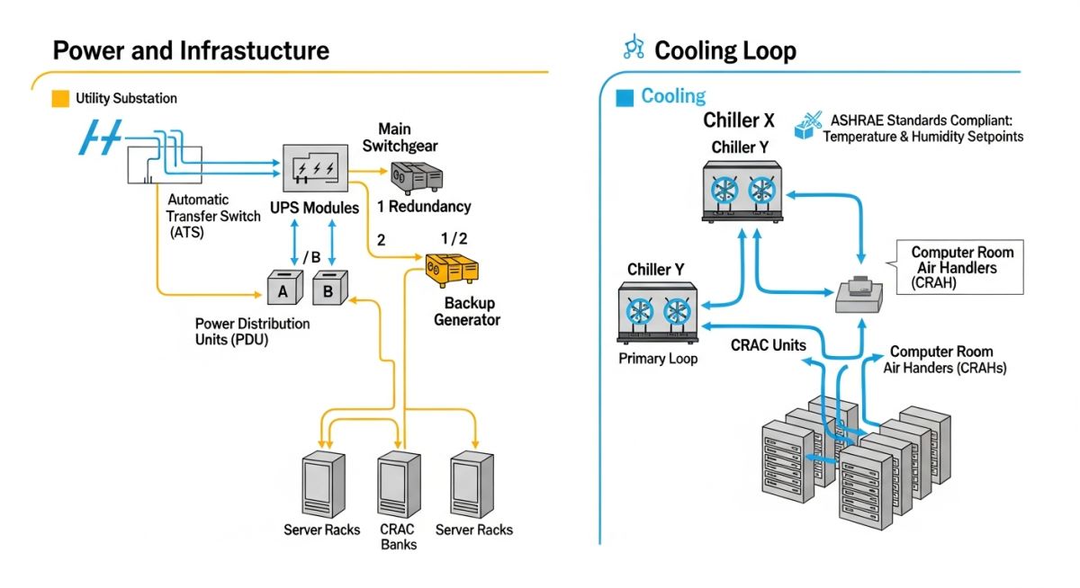
Designing for high availability requires a deep understanding of the heat rejection cycle. In a typical facility, the heat generated by server racks is captured by Computer Room Air Handlers (CRAH) or Computer Room Air Conditioners (CRAC). The cooling medium, usually chilled water, must be circulated through a redundant piping network that adheres to ASME B31.3 process piping standards to prevent leaks that could destroy sensitive hardware.
Thermal Load Calculations and Fluid Dynamics
To calculate the required chilled water flow rate, we utilize the fundamental heat transfer equation: Q = m * Cp * deltaT. In this context, Q represents the total heat load of the server hall in kilowatts, m is the mass flow rate of the coolant, Cp is the specific heat capacity of the fluid (typically a water-glycol mixture), and deltaT is the temperature differential between supply and return lines.
Engineering Warning: Fluid Velocity Limits
In piping design for data centres, maintaining fluid velocity between 3 and 8 feet per second is critical. Velocities exceeding 10 feet per second significantly increase the risk of erosion-corrosion in copper or steel piping, while velocities below 2 feet per second can lead to sediment buildup and air pocket entrapment, causing localized hot spots in the cooling loop.
Power distribution is equally critical. We design for 2N redundancy, meaning two independent power paths are available at all times. This involves dual-feed UPS systems and automatic transfer switches (ATS) that must be coordinated with the facility’s backup generator plant. The electrical load calculation must account for the Power Usage Effectiveness (PUE) ratio, which is the total facility power divided by the IT equipment power. A PUE approaching 1.0 is the industry gold standard, achieved through advanced economization and high-efficiency power conversion.
Structural considerations also play a role, particularly with raised floor systems. These floors must support the immense weight of server racks while allowing for the unobstructed flow of cold air. The pressure differential between the under-floor plenum and the room must be carefully managed to ensure uniform air distribution across all rack intakes, preventing thermal bypass where cold air escapes without cooling the equipment.
Data Centre Infrastructure Trade-offs: The engineering balance between capital expenditure, operational reliability, and energy efficiency in high-density computing environments.
Advantages
- High-availability designs ensure 99.999% uptime for critical services.
- Scalable modular infrastructure allows for incremental capacity expansion.
- Advanced cooling technologies like liquid immersion improve energy efficiency.
- Centralized management reduces the footprint of distributed IT assets.
Disadvantages
- Extremely high initial capital expenditure for redundant systems.
- Complex maintenance requirements for mechanical and electrical loops.
- Significant environmental impact due to high water and power consumption.
- Risk of single-point failure if redundancy protocols are not strictly followed.
Data Centre Deployment Scenarios: The application of high-availability infrastructure across diverse sectors requiring secure, scalable, and resilient computing power.
Financial Services High-Frequency Trading
Financial institutions require ultra-low latency environments where data centre infrastructure is optimized for microsecond processing speeds. This involves specialized cooling for high-density compute clusters and dedicated power conditioning to eliminate electromagnetic interference.
Cloud Service Provider Hyperscale Facilities
Hyperscale data centres serve global internet traffic, requiring massive scale and extreme energy efficiency. These facilities utilize large-scale economization and advanced water-side free cooling to minimize the PUE and reduce operational costs at scale.
Healthcare Electronic Health Record Management
Healthcare providers must maintain strict data privacy and availability for patient records. These data centres are designed with robust fire suppression and physical security protocols, ensuring that critical medical data remains accessible during facility-wide power outages.
In my two decades of experience, the design of high-availability facilities hinges on the precise selection of mechanical and electrical components. Engineers must balance the Power Usage Effectiveness (PUE) against the total cost of ownership, ensuring that every component—from the chiller plant to the uninterruptible power supply (UPS)—operates within its optimal efficiency curve. The following table outlines the standard performance benchmarks I utilize when evaluating facility infrastructure for Tier III and Tier IV data centres.
These metrics are not merely theoretical; they represent the operational reality of maintaining 99.995% uptime. When reviewing these values, consider the impact of ambient temperature fluctuations and load density on the overall system reliability. Always cross-reference these parameters with the latest ASHRAE TC 9.9 guidelines to ensure your cooling strategy aligns with current server hardware thermal envelopes.
| System Component | Metric/Parameter | Industry Standard |
|---|---|---|
| Chiller Plant | Coefficient of Performance (COP) | Greater than 6.0 |
| UPS System | Double Conversion Efficiency | 96% to 98% |
| Power Distribution | Voltage Regulation Tolerance | Plus or minus 5% |
| Cooling Distribution | Supply Air Temperature | 18 to 27 Degrees Celsius |
By maintaining these specific thresholds, engineers can significantly reduce the risk of thermal runaway or power instability. I strongly recommend implementing real-time monitoring systems that trigger automated alerts when any of these parameters deviate from the established baseline, as early detection is the primary defense against catastrophic downtime.
The complexity of modern facility design requires a structured approach to mapping physical infrastructure to regulatory standards. As an engineer, I find that maintaining a clear matrix of components, their associated acronyms, and the governing codes is vital for project documentation and compliance audits. This matrix serves as a foundational reference for cross-disciplinary teams, ensuring that mechanical, electrical, and plumbing (MEP) systems are integrated seamlessly.
Each entity listed below is subject to rigorous testing protocols defined by international bodies. When specifying these components, ensure that your design documentation explicitly references the relevant ANSI or IEEE standards to avoid procurement errors. This mapping is particularly useful during the commissioning phase, where verification of each system’s performance against its design intent is mandatory.
| Entity | Acronym | Standard Reference |
|---|---|---|
| Computer Room Air Handler | CRAH | ASHRAE 90.4 |
| Power Distribution Unit | PDU | IEC 60950 |
| Automatic Transfer Switch | ATS | NFPA 110 |
| Building Management System | BMS | BACnet/IP |
Utilizing this matrix during the design development phase allows for better coordination between the electrical and mechanical trades. It prevents the common pitfall of mismatched capacity ratings, which often leads to significant delays during the final integration and testing stages of the project lifecycle.
Facility Infrastructure Verification: Before final handover, every system must undergo a rigorous validation process to ensure it meets the design specifications and safety requirements. In my experience, the following checklist is the most effective way to identify potential failure points before they impact live operations.
-
[ ]
Redundancy Verification: Confirm that all N+1 or 2N configurations are physically isolated to prevent common-mode failures. -
[ ]
Thermal Load Testing: Execute a full-load heat rejection test to verify that the cooling system maintains setpoints under peak server demand. -
[ ]
Power Quality Audit: Measure harmonic distortion and voltage stability at the PDU level to ensure compliance with IEEE 519. -
[ ]
Fire Suppression Integration: Validate that the gaseous fire suppression system is interlocked with the HVAC controls to prevent oxygen depletion. -
[ ]
Grounding and Bonding: Inspect all signal reference grids to ensure resistance levels are within the manufacturer’s specified tolerance.
Each item on this checklist must be signed off by both the lead mechanical and electrical engineers. If a test fails, the system must be re-commissioned from the component level upward. Never bypass these steps, as the cost of a post-commissioning failure far outweighs the time required for thorough site verification.
Field Case Study: Real-World Application
The Problem: Thermal Stratification in High-Density Rows
A Tier III facility experienced localized hot spots in high-density server rows, leading to intermittent hardware throttling despite the overall room temperature being within the ASHRAE recommended range.
- Inadequate floor tile perforation ratios in the cold aisle.
- Airflow bypass caused by unsealed cable cutouts under the raised floor.
- Improper placement of temperature sensors relative to the server intake.
- CRAH units operating at inconsistent fan speeds across the row.
The Outcome: Optimized Airflow and Thermal Stability
By implementing a comprehensive airflow management strategy, we successfully eliminated the hot spots and improved the overall cooling efficiency of the facility.
- Increased PUE by 0.08 through the installation of blanking panels and floor grommets.
- Standardized sensor placement at the 1.5-meter height for accurate intake monitoring.
- Implemented variable frequency drives on all CRAH fans to match load demand.
- Achieved a 15% reduction in total energy consumption for the cooling plant.
My recommendation for similar scenarios is to prioritize physical airflow containment before investing in additional cooling capacity. Often, the issue is not a lack of cooling, but rather the inefficient delivery of the air to the server intake, which can be corrected with simple, low-cost infrastructure modifications.
Frequently Asked Engineering Questions
What is the primary difference between Tier III and Tier IV designs?
- Tier III requires a single active distribution path.
- Tier IV requires multiple active distribution paths.
- Tier IV mandates continuous cooling for all critical components.
How does PUE impact the long-term operational cost?
- High PUE values indicate inefficient cooling or power distribution.
- Reducing PUE by even 0.1 can save millions in electricity costs over a decade.
- Modern designs aim for a PUE below 1.3 in temperate climates.
Why is ASHRAE TC 9.9 critical for HVAC design?
- It prevents over-cooling, which is a common source of energy waste.
- It provides guidance on humidity control to prevent electrostatic discharge.
- It is the industry standard for warranty compliance with server manufacturers.
What are the risks of improper grounding in a facility?
- Ground loops can cause data corruption in high-speed communication lines.
- Lack of proper bonding increases the risk of electrical shock during maintenance.
- Compliance with NFPA 70 is mandatory for all electrical installations.
How do I select the right UPS topology?
- It eliminates transfer time during power outages.
- It provides a clean, regulated sine wave output.
- It allows for seamless integration with backup generator systems.
What is the role of a Building Management System?
- It optimizes energy usage by adjusting cooling based on real-time load.
- It provides historical data for predictive maintenance planning.
- It ensures that all systems operate within their safe design parameters.
Complete Course on
Piping Engineering
Check Now
Key Features
- 125+ Hours Content
- 500+ Recorded Lectures
- 20+ Years Exp.
- Lifetime Access
Coverage
- Codes & Standards
- Layouts & Design
- Material Eng.
- Stress Analysis

Related posts:
![Technical infographic showing the workflow of flood risk assessment for data centres, including hydrological inputs and mitigation strategies.]()
Flood Risk Assessment for Data Centres: Engineering Design Guide
![Isometric engineering rendering of a data centre campus featuring flood protection barriers and elevated utility infrastructure for disaster resilience.]()
Flood Protection Level Selection for Mission-Critical Data Centre Infrastructure
![Cross-section diagram of a data centre foundation showing soil strata, pile foundations, and groundwater monitoring wells for geotechnical analysis.]()
Geotechnical Requirements for Data Centres: A Structural Engineering Guide
![Civil 3D interface showing a 3D site grading model with color-coded cut and fill zones for earthwork optimization.]()
Optimizing Cut and Fill Operations Using Civil 3D and GIS
![3D digital terrain model showing site grading, flood protection levels, and cut-fill zones for industrial infrastructure development.]()
Establishing FPL and Estimating Cut Fill Quantities for Site Grading
![3D engineering model showing cut and fill optimization for industrial site grading and earthwork balancing.]()
Cut and Fill Optimization: 8 Engineering Studies for Site Grading