Table of Contents
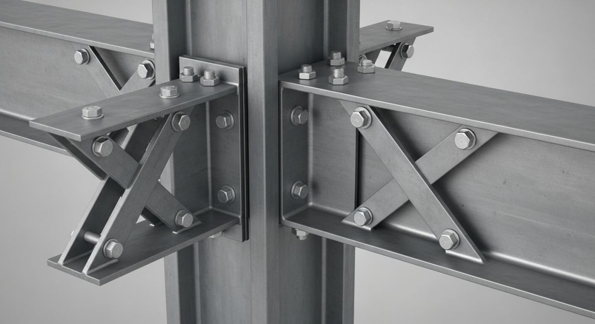
Mastering Steel Connections with a Cross-Bracing Design Example
In my 20 years of structural and piping design, I have seen many engineers struggle with the interface where structural steel meets high lateral loads. Cross-bracing is the backbone of lateral force-resisting systems in industrial plants, refineries, and multi-story buildings. However, a bracing member is only as strong as its connection. If you do not design the gusset plate, bolts, and welds to handle the complex distribution of forces, the entire system can fail catastrophically.
This guide walks you through a comprehensive, real-world design scenario. We will break down the math, apply the governing codes, and look at the practical field realities that textbooks often ignore. My goal is to give you a clear, step-by-step roadmap that you can immediately apply to your projects.
Key Takeaways
- Understand how to apply the Uniform Force Method (UFM) to distribute interface forces without inducing unwanted moments.
- Learn to calculate the Whitmore Section width to verify gusset plate yielding and buckling limits.
- Master the design of welded and bolted interfaces under combined shear and tensile forces.
- Discover how to avoid common field installation errors that compromise connection capacity.
Step-by-Step Cross-Bracing Design Example Calculations
Bracing Connection Calculations: The analytical verification of gusset plates, weld sizes, and bolt groups under tension and compression limits. These calculations utilize the Uniform Force Method to distribute interface forces in compliance with AISC Design Guide 29.
Let us dive into a practical design scenario. We will design a diagonal cross-bracing connection for an industrial pipe rack. The bracing member is subjected to both high tension and compression forces due to wind and seismic loads.
1. Design Parameters and Material Properties
Before starting the calculations, we must establish our design constraints and material properties. For this example, we will use the following parameters:
- Bracing Member: HSS 6x6x3/8 (ASTM A500 Grade C, Fy = 50 ksi, Fu = 62 ksi)
- Factored Design Load (Pu): 180 kips (Tension and Compression)
- Brace Angle (theta): 45 degrees relative to the horizontal beam
- Gusset Plate: ASTM A36 (Fy = 36 ksi, Fu = 58 ksi), initial thickness (tg) assumed as 0.5 inches
- Supporting Beam: W12x50 (ASTM A992, Fy = 50 ksi, Fu = 65 ksi, depth d = 12.2 inches, flange thickness tf = 0.64 inches)
- Supporting Column: W12x65 (ASTM A992, Fy = 50 ksi, Fu = 65 ksi, depth d = 12.1 inches, flange thickness tf = 0.605 inches)
- Connection Type: Welded HSS to gusset plate, with the gusset plate welded to the beam and column flanges.
2. Tension Yielding and Rupture of the Brace
First, we must verify that the HSS 6x6x3/8 member itself can handle the 180-kip tension load.
The gross area (Ag) of an HSS 6x6x3/8 is 7.58 square inches.
Tension Yielding Limit State:
Phi * Pn = Phi * Fy * Ag
Phi * Pn = 0.90 * 50 ksi * 7.58 sq. in. = 341.1 kips
Since 341.1 kips is greater than 180 kips, tension yielding is not a governing failure mode.
Tension Rupture Limit State (Shear Lag):
Because the HSS is slotted and welded to the gusset plate, we must account for shear lag. The shear lag factor (U) is calculated using the formula:
U = 1 – (x_bar / L)
Where x_bar is the connection eccentricity (for a single plate in a slotted HSS, x_bar is approximately 2.32 inches) and L is the weld length. Let us assume a weld length (L) of 8 inches.
U = 1 – (2.32 / 8) = 0.71
Effective Net Area (Ae) = Ag * U = 7.58 * 0.71 = 5.38 square inches.
Phi * Pn = Phi * Fu * Ae = 0.75 * 62 ksi * 5.38 sq. in. = 250.2 kips
Since 250.2 kips is greater than 180 kips, the brace is safe against tensile rupture.
3. Gusset Plate Evaluation (Whitmore Section)
The Whitmore Section defines the effective width of the gusset plate acting in tension or compression. It is determined by drawing 30-degree lines outward from the start of the connection weld to the end of the weld.
The Whitmore width (Lw) is calculated as:
Lw = Weld Spacing + 2 * L * tan(30)
Where Weld Spacing is the width of the HSS (6 inches) and L is the weld length (8 inches).
Lw = 6 + 2 * 8 * 0.577 = 15.23 inches.
Whitmore Yielding Capacity (Tension/Compression):
Phi * Rn = Phi * Fy * Lw * tg
Phi * Rn = 0.90 * 36 ksi * 15.23 in. * 0.5 in. = 246.7 kips
Since 246.7 kips is greater than 180 kips, the gusset plate is adequate for yielding.
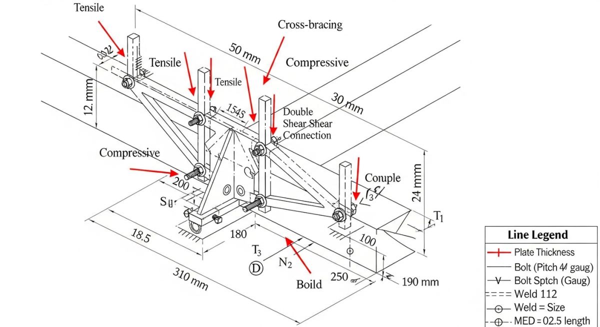
4. Gusset Plate Buckling under Compression
When the brace goes into compression, the gusset plate can buckle. We treat the unbraced portion of the gusset plate as a column. The effective length (Lc) is the distance from the end of the brace to the beam-to-column interface along the line of action.
Let us assume an unbraced length (L_unbraced) of 4 inches. According to AISC guidelines, we use an effective length factor (K) of 1.2 for a single gusset plate connection.
Radius of gyration (r) of the 0.5-inch plate = tg / sqrt(12) = 0.5 / 3.46 = 0.144 inches.
Slenderness ratio (KL/r) = 1.2 * 4 / 0.144 = 33.3
Using AISC Chapter E, we calculate the critical buckling stress (Fcr). For KL/r = 33.3, the plate is in the inelastic buckling zone.
Fe = (pi^2 * E) / (KL/r)^2 = (3.1416^2 * 29000) / 33.3^2 = 258.3 ksi
Fcr = [0.658^(Fy/Fe)] * Fy = [0.658^(36/258.3)] * 36 = 33.9 ksi
Nominal Buckling Strength (Pn) = Fcr * Lw * tg = 33.9 ksi * 15.23 in. * 0.5 in. = 258.1 kips
Design Buckling Strength (Phi * Pn) = 0.90 * 258.1 kips = 232.3 kips
Since 232.3 kips is greater than 180 kips, the gusset plate will not buckle under the design compression load.
5. Uniform Force Method (UFM) Interface Forces
The Uniform Force Method is the industry standard for distributing forces to the gusset-to-beam and gusset-to-column interfaces without creating eccentric moments. The geometry must satisfy the following constraint:
alpha – beta * tan(theta) = eb – ec * tan(theta)
Where:
eb = half the beam depth = 12.2 / 2 = 6.1 inches
ec = half the column depth = 12.1 / 2 = 6.05 inches
theta = 45 degrees (tan(45) = 1.0)
Let us select a trial gusset plate geometry where alpha (distance from column centerline to gusset-to-beam weld centroid) is 12 inches.
12 – beta * 1.0 = 6.1 – 6.05 * 1.0
12 – beta = 0.05
beta = 11.95 inches (distance from beam centerline to gusset-to-column weld centroid).
With these parameters, we calculate the interface forces:
Radial distance (R) = sqrt((alpha + ec)^2 + (beta + eb)^2) = sqrt((12 + 6.05)^2 + (11.95 + 6.1)^2) = 25.5 inches.
Force on Beam Interface:
Shear (Vb) = (eb / R) * Pu = (6.1 / 25.5) * 180 = 43.1 kips
Normal Force (Hb) = (alpha / R) * Pu = (12 / 25.5) * 180 = 84.7 kips
Force on Column Interface:
Shear (Vc) = (beta / R) * Pu = (11.95 / 25.5) * 180 = 84.4 kips
Normal Force (Hc) = (ec / R) * Pu = (6.05 / 25.5) * 180 = 42.7 kips
These forces are now used to design the welds connecting the gusset plate to the beam and column. By using the UFM, we ensure that no bending moments are introduced at these critical interfaces, which simplifies the design and increases safety.
Gusset Plate Parameters: The standardized geometric and material limits used to prevent premature buckling or tearing of connection plates. These values align with ASTM A36 and ASTM A572 Grade 50 steel standards.
| Plate Thickness (inches) | Material Grade | Max Factored Load (kips) | Min Weld Size (E70XX) | Recommended Application |
|---|---|---|---|---|
| 3/8 (0.375) | ASTM A36 | 120 | 1/4″ Fillet | Light industrial frames, secondary bracing |
| 1/2 (0.500) | ASTM A36 / A572 Gr 50 | 220 | 5/16″ Fillet | Standard pipe racks, medium process structures |
| 5/8 (0.625) | ASTM A572 Grade 50 | 350 | 3/8″ Fillet | Heavy industrial, dynamic equipment support |
| 3/4 (0.750) | ASTM A572 Grade 50 | 500+ | 1/2″ Fillet / CJP | High-seismic zones, heavy multi-story columns |
| Design Entity | Governing Code | Key Parameter | Acceptance Criteria |
|---|---|---|---|
| Brace Tension Yielding | AISC 360-16 Chapter D | Gross Area (Ag) | Phi = 0.90, Pu <= Phi * Fy * Ag |
| Brace Tension Rupture | AISC 360-16 Chapter D | Shear Lag Factor (U) | Phi = 0.75, Pu <= Phi * Fu * Ae |
| Gusset Buckling | AISC 360-16 Chapter E | Whitmore Width (Lw) | Phi = 0.90, Pu <= Phi * Fcr * Ag_gusset |
| Weld Strength | AWS D1.1 / AISC Chapter J | Electrode Strength (Fexx) | Phi = 0.75, Ru <= Phi * 0.60 * Fexx * Aw |
Field Inspection Protocols: The mandatory quality control steps executed on-site to verify that physical bracing installations match approved engineering drawings. These checks focus on bolt torque, weld profiles, and structural alignment per AISC COSP.
Even the most perfect calculations on paper will fail if the field execution is poor. In my experience, many connection failures are caused by simple installation oversights. Use this checklist on-site to verify that your cross-bracing connections are built exactly as designed.
On-Site Verification Checkpoints
-
Gusset Plate Alignment: Verify that the gusset plate is perfectly coplanar with the centerline of the bracing member. Out-of-plane eccentricity introduces severe bending moments that can cause premature buckling.
-
Weld Size and Profile: Measure the fillet weld sizes using a weld gauge. Ensure that the weld length matches the design drawings (e.g., 8 inches in our design example) and that there is no undercut or porosity.
-
Bolt Tensioning (if bolted): For bolted connections, verify that all high-strength bolts (ASTM F3125 Grade A325 or A490) are tensioned using the turn-of-nut method or calibrated wrench method. Check for proper washer placement.
-
Clearance for Buckling: Ensure that the “2t” clearance rule is maintained. The end of the bracing member should be terminated at a distance of at least twice the gusset plate thickness from the line of restraint to allow the plate to yield plastically during a seismic event.
-
Material Traceability: Cross-reference the Mill Test Reports (MTRs) for the gusset plates and bracing members to ensure they match the specified ASTM grades (e.g., ASTM A36 or A572 Grade 50).
Field Case Study: Real-World Application
Field Case Study Analysis: A real-world evaluation of a structural failure risk during a refinery expansion and the subsequent engineering intervention. This study demonstrates the practical application of the Uniform Force Method to resolve geometric interference.
The Problem: Geometric Interference and Eccentric Loading
During a major refinery expansion in 2024, a field construction team encountered a severe clash. A newly routed high-pressure steam line was running directly through the space reserved for a diagonal cross-bracing member on a critical pipe rack. To bypass the pipe, the field subcontractor modified the gusset plate on-site without engineering approval. They shifted the bracing member’s work point by 8 inches, creating a massive eccentricity at the beam-column joint.
This modification introduced a large bending moment into a column that was already heavily loaded. During a routine site walkdown, I noticed the offset connection. The column was showing early signs of localized flange yielding under wind-induced lateral loads.
The Outcome: Redesign and Retrofitting
I immediately ordered a halt to work in that bay and modeled the eccentric connection. The analysis showed that the column flange was overstressed by 42% due to the unapproved eccentricity.
To resolve the issue without rerouting the steam line, we redesigned the connection using the Uniform Force Method. We designed a new, extended gusset plate that incorporated a wrapper plate on the column flange to distribute the eccentric moment. We also added horizontal stiffener plates (continuity plates) inside the column web to prevent web yielding. The field team cut out the modified gusset and installed the new engineered connection. Subsequent laser-monitoring confirmed that the column stresses returned to safe, allowable limits.
This case study highlights why you must never allow field modifications to structural connections without running the math. A simple shift of a work point can completely change the load path and lead to localized structural failure.
Frequently Asked Engineering Questions
Bracing Connection FAQs: Expert answers to common technical queries regarding the design, analysis, and installation of steel cross-bracing systems. These responses reference AISC 360-16 and modern structural engineering practices.
What is the Uniform Force Method (UFM) and why is it preferred?
How do you determine the Whitmore Section width?
Why is the “2t” clearance rule important for gusset plates?
Can I use bolt groups instead of welds for cross-bracing?
How does shear lag affect slotted HSS bracing connections?
What happens if the brace angle is not 45 degrees?
Complete Course on
Piping Engineering
Check Now
Key Features
- 125+ Hours Content
- 500+ Recorded Lectures
- 20+ Years Exp.
- Lifetime Access
Coverage
- Codes & Standards
- Layouts & Design
- Material Eng.
- Stress Analysis

📚 Recommended Resources: design example
Read these Guides
🎓 Advanced Training

Related posts:
![Infographic flowchart of the GRP GRE FRP piping stress analysis workflow in START-PROF.]()
Rigid Struts: Definition, Applications, and Modeling in Caesar II
![3D stress analysis model of GRP piping system in START-PROF software showing stress distribution.]()
Stress Analysis of GRP / GRE / FRP Piping using START-PROF
![Industrial centrifugal pump installed on a concrete foundation with precision piping and alignment.]()
How to Use a Pump Installation Checklist for Maximum Reliability
![3D Caesar II pipe stress analysis model of a centrifugal pump piping system showing stress distribution.]()
Pump-Piping Alignment Caesar II Stress Analysis Methodology
![Industrial engineer checking shaft alignment on a centrifugal pump during commissioning.]()
How to Use a Pump Commissioning Checklist for Start-Up
![3D FEA model of a piping system showing modal analysis vibration shapes and stress distribution.]()
What Is Modal Analysis? Caesar II Piping Modal Analysis Steps