Table of Contents
Comprehensive Guide to Corrosion Inhibitors in the Oil and Gas Industry
In my 20-plus years of piping engineering, I have stood on offshore platforms and in desert processing facilities looking at pipelines eaten away from the inside out. Internal corrosion is a silent, relentless enemy. When you are dealing with wet gas, sour crude, or high-water-cut production fluids, relying solely on corrosion allowance is a recipe for disaster. That is where chemical treatment becomes your primary line of defense.
Implementing chemical treatment is not just about pumping a generic chemical down a wellbore or into a manifold. It requires a deep understanding of fluid dynamics, metallurgy, and chemical partitioning. In this guide, I will share the practical engineering principles, calculations, and field-proven strategies needed to select, design, and monitor chemical injection systems that keep your infrastructure intact.
Key Engineering Takeaways
- Understand how filming amines establish a hydrophobic barrier to block corrosive species.
- Learn to calculate inhibitor efficiency and evaluate wall shear stress limits.
- Master the selection criteria based on temperature, fluid velocity, and sour service conditions.
- Implement robust field monitoring protocols using electrical resistance probes and coupon analysis.
Complete Course on
Piping Engineering
Check Now
Key Features
- 125+ Hours Content
- 500+ Recorded Lectures
- 20+ Years Exp.
- Lifetime Access
Coverage
- Codes & Standards
- Layouts & Design
- Material Eng.
- Stress Analysis
Why Corrosion Inhibitors in Oil and Gas Matter
Internal corrosion in oil and gas pipelines is primarily driven by the presence of water alongside carbon dioxide (CO2, sweet corrosion), hydrogen sulfide (H2S, sour corrosion), and oxygen. When these gases dissolve in the aqueous phase, they form highly corrosive acids. For instance, dissolved CO2 forms carbonic acid, which rapidly attacks carbon steel, leading to severe pitting.
To quantify the performance of your chemical treatment program, you must calculate the Inhibitor Efficiency (IE%). This is the fundamental metric I use to evaluate whether a chemical formulation is performing up to design specifications:
Where:
• CR_uninhibited is the baseline corrosion rate of the bare metal without chemical treatment (typically measured in millimeters per year, mm/y, or mils per year, mpy).
• CR_inhibited is the corrosion rate measured after the continuous injection of the chemical inhibitor.
In high-velocity pipelines, fluid shear stress at the pipe wall can physically strip away the protective inhibitor film. Therefore, we must calculate the wall shear stress (tau) to ensure it does not exceed the critical shear stress limit of the selected chemical:
Where:
• tau is the wall shear stress (Pascals, Pa).
• f is the dimensionless Fanning friction factor, determined via the Moody diagram or Colebrook-White equation.
• rho is the fluid density (kg/m³).
• v is the mean fluid velocity (m/s).
If your calculated wall shear stress exceeds the manufacturer’s certified limit (often ranging from 10 to 50 Pa for standard filming amines), the inhibitor film will fail, leading to localized, accelerated pitting.
How Corrosion Inhibitors in Oil and Gas Work
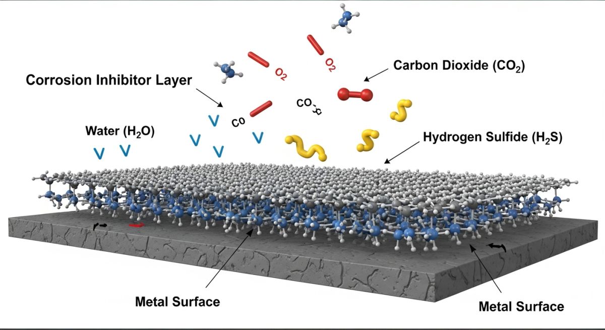
Most commercial formulations used in our industry are organic, surface-active compounds. These molecules consist of a polar “head” group and a non-polar, hydrophobic hydrocarbon “tail”. The polar head group contains heteroatoms such as nitrogen (in imidazolines or quaternary ammonium salts), sulfur, or phosphorus. These atoms possess free electron pairs that form coordinate covalent bonds with the d-orbitals of the iron atoms on the steel surface.
Once the polar head adsorbs onto the metal, the hydrophobic hydrocarbon tails align parallel to each other, projecting outward into the fluid phase. This creates a dense, water-repellent barrier that prevents water molecules, hydronium ions, and corrosive dissolved gases from reaching the metal surface.
We classify these chemicals into three primary categories based on their electrochemical behavior:
- Anodic Inhibitors: These shift the corrosion potential of the metal into the passive region by promoting the formation of a protective oxide or hydroxide layer. They typically react with the metal ions to form insoluble precipitates. However, if the dosage is insufficient, incomplete coverage can lead to severe localized pitting.
- Cathodic Inhibitors: These migrate to cathodic sites on the metal surface and selectively slow down the reduction reactions (such as hydrogen evolution or oxygen reduction). They do this by forming a physical barrier or by increasing the activation energy barrier for the electron transfer process.
- Mixed Inhibitors: The vast majority of organic filming inhibitors used in upstream production behave as mixed inhibitors. They adsorb non-selectively across both anodic and cathodic sites, reducing the overall rate of both electrochemical half-reactions. This makes them far safer to use, as under-dosing does not trigger localized pitting.
Selecting the correct chemical formulation requires matching the chemical’s physical properties with the operating envelope of your piping system. The table below outlines the typical performance limits and application guidelines for the most common chemical classes used in upstream and midstream assets.
| Chemical Class | Temp Limit (°C) | Dosage Range (ppm) | Primary Application | Applicable Standards |
|---|---|---|---|---|
| Imidazolines | Up to 120 | 10 – 50 | Wet crude, CO2-dominated systems | NACE SP0169 |
| Quaternary Amines | Up to 150 | 5 – 30 | Sour service (H2S), water injectors | NACE MR0175 / ISO 15156 |
| Phosphate Esters | Up to 180 | 15 – 75 | High-temperature gas wells, scale/corr combo | ASTM G170 |
| Polymer Filming Agents | Up to 200 | 20 – 100 | Ultra-deepwater, high-shear flowlines | API RP 14E |
This matrix maps the core technical entities, structural acronyms, and physical parameters that you must specify during the engineering design phase of a chemical injection system.
| Entity / Parameter | Acronym | Physical Unit | Design Significance | Reference Standard |
|---|---|---|---|---|
| Partition Coefficient | K_ow | Dimensionless | Determines chemical distribution between oil and water phases | ASTM E1148 |
| Minimum Inhibitor Concentration | MIC | mg/L (ppm) | The lowest concentration required to maintain the protective film | NACE TM0182 |
| Linear Polarization Resistance | LPR | mm/y or mpy | Real-time electrochemical measurement of instantaneous corrosion | ASTM G59 |
| Electrical Resistance Probe | ER | Microns (loss) | Measures physical metal loss over time in non-conductive fluids | NACE SP0775 |
Field Verification of Chemical Injection Systems
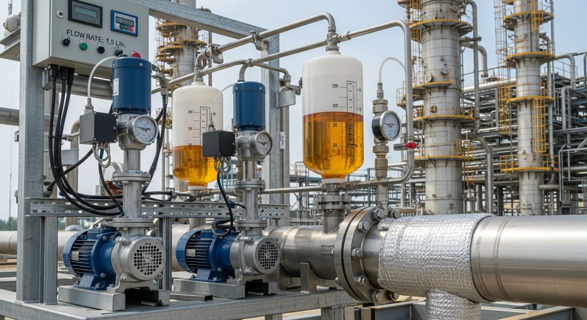
A chemical treatment program is only as good as its delivery system. If your injection pump loses prime, or if your injection quill is positioned incorrectly, you will end up with unprotected pipe sections and rapid localized failures. In my experience, regular field audits of the injection skid and monitoring hardware are the only way to guarantee long-term pipeline integrity.
Pre-Commissioning & Operations Checklist
-
Quill Orientation & Depth: Verify that the injection quill extends into the center one-third of the pipe diameter. Ensure the bevel of the quill faces upstream to maximize atomization and chemical dispersion.
-
Pump Calibration: Perform a drawdown calibration test on the positive displacement dosing pump. Verify that the actual flow rate matches the target dosage (ppm) based on current pipeline production rates.
-
Solvent Compatibility: Confirm that all elastomer seals, O-rings, and diaphragms in the injection pump and piping manifold are chemically compatible with the inhibitor carrier solvent (e.g., methanol, xylene, or heavy aromatic naphtha) per API Standard 675.
-
Backpressure & Relief Valves: Test the functionality of the inline backpressure valve and the safety relief valve. The relief valve must be set to vent back to the chemical storage tank if the injection line becomes plugged.
-
Monitoring Probe Alignment: Ensure that the corrosion coupons and ER probes are installed in the 6 o’clock position for liquid-settling lines, or the 12 o’clock position if top-of-line corrosion is the primary threat.
Field Case Study: Real-World Application
The Problem: Severe Pitting in a Wet Gas Pipeline
A 16-inch carbon steel wet gas pipeline in the Middle East, operating at 85 bar and 65°C, experienced rapid wall thinning. The gas contained 3.5 mol% CO2 and 150 ppm H2S, with a water condensation rate of 12 barrels per million standard cubic feet. Despite continuous injection of a standard water-soluble filming amine at 25 ppm, ultrasonic testing revealed localized pitting rates exceeding 1.8 mm/year.
Our engineering audit revealed two critical flaws: first, the high fluid velocity (14 m/s) generated a wall shear stress of 38 Pa, which was stripping the water-soluble inhibitor film. Second, the chemical was partitioning poorly into the condensing water phase at the top of the pipe, leaving the upper quadrant completely unprotected against top-of-line corrosion.
The Solution & Outcome
I led the engineering team to redesign the chemical treatment strategy. We replaced the water-soluble amine with a high-shear-resistant, oil-soluble/water-dispersible filming imidazoline formulation. This new chemical possessed a critical shear stress limit of 65 Pa, well above our operating shear stress.
We also replaced the standard injection quill with an atomizing spray nozzle that projected a fine mist directly into the gas stream, ensuring the chemical reached the top of the pipe. We installed real-time ER probes and high-resolution corrosion coupons to monitor the results. Within 30 days, the measured corrosion rate dropped from 1.8 mm/year to a stable 0.03 mm/year, extending the design life of the pipeline by an estimated 25 years.
Direct Engineering Recommendation: Never select an inhibitor based solely on static laboratory bottle tests. Always perform dynamic autoclave testing or loop testing under simulated field shear stress and temperature conditions to verify film persistence before purchasing bulk chemicals.
Frequently Asked Engineering Questions
What is the difference between water-soluble and oil-soluble inhibitors?
How does H2S concentration affect chemical selection?
Can corrosion inhibitors cause foaming in downstream processing?
What is the typical design life of an injection quill?
How do glycol or methanol injections impact inhibitor performance?
What are the environmental regulations regarding offshore chemical discharge?

📚 Recommended Resources: corrosion inhibitors in oil and gas
Related posts:
![Industrial worker welding a large structural steel I-beam in a fabrication facility.]()
What is Structural Steel Fabrication and How Does It Work?
![A heavy-duty stainless steel turnbuckle tensioning a structural cable.]()
What is a Turnbuckle and How to Install It?
![Stack of newly manufactured galvanized steel pipes in an industrial warehouse]()
Understanding the Galvanized Pipe Meaning in Modern Piping Systems
![Industrial Alloy 625 piping components in a manufacturing plant]()
What is Alloy 625? Properties, Grades, and Applications of Alloy 625
![Close-up of a fractured steel shaft showing metal fatigue beach marks and failure zones.]()
What is Metal Fatigue and How Do Engineers Prevent It?
![Industrial machinery fitted with smart sensors displaying real-time condition-based maintenance data on a digital overlay.]()
What is Condition-Based Maintenance and How Does It Work?