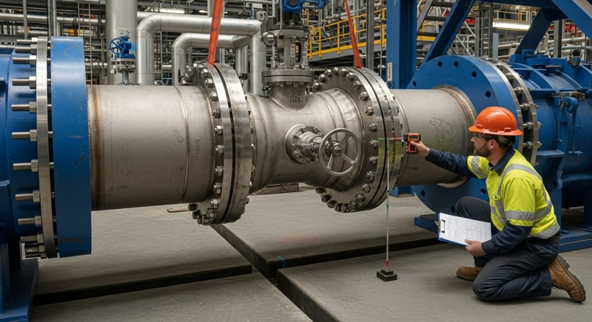
Cold Pull: Precision Stress Management in Piping Systems
In my two decades of field experience, I have seen countless piping systems fail prematurely due to excessive nozzle loads. Cold pull is a classic, yet often misunderstood, mechanical technique used to pre-stress a piping system during installation. By intentionally cutting a pipe spool shorter or longer than the theoretical gap, we force the system into a state of initial tension or compression.
When the system reaches its design temperature, the thermal expansion effectively “relaxes” this pre-stress, bringing the piping closer to a neutral state at operating conditions. While this sounds straightforward, the site execution requires rigorous control to avoid creating new, unintended stress concentrations. This guide explores the mechanics, the risks, and the site-level realities of applying cold pull effectively.
Key Takeaways for Field Engineers:
- Cold pull is primarily used to reduce forces and moments on sensitive rotating equipment nozzles.
- The technique is governed by ASME B31.3, which mandates that the design must account for the pre-stress state.
- Improper site execution can lead to permanent deformation or flange leakage during startup.
- Always document the “as-installed” cold pull values in the final piping stress report.
Technical Mechanics of Cold Pull in Piping
Cold Pull Engineering Principles: The application of cold pull involves the deliberate modification of a piping spool length to introduce a calculated amount of pre-stress, effectively shifting the stress range from the cold condition to the hot operating condition.
When we perform a cold pull, we are essentially manipulating the displacement vector of the piping system. In a typical scenario, a pipe is designed to expand by a value of delta-L. By installing the pipe with a cold pull of 50 percent of delta-L, we introduce an initial stress that is opposite in sign to the thermal stress. As the pipe heats up, the thermal expansion consumes the pre-stress, resulting in a lower net stress at the operating temperature.
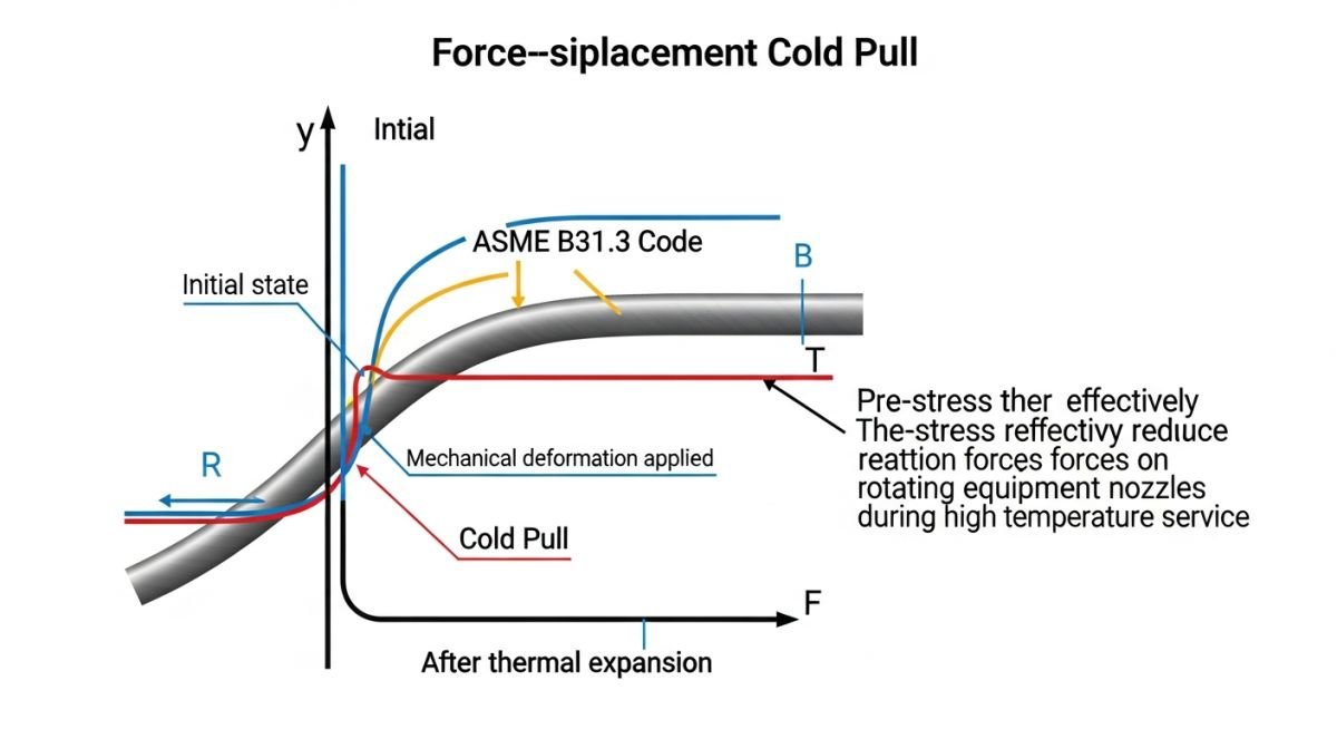
The calculation for the required cold pull is derived from the thermal expansion analysis. If the total thermal expansion is delta-T, the cold pull (CP) is typically defined as a percentage of this value, often ranging from 50 percent to 100 percent. The formula for the force required to close the gap is F = (k * CP), where k represents the stiffness of the piping system in the direction of the pull.
Field Warning: The Stiffness Trap
Never assume the piping system is a simple spring. The stiffness (k) is highly dependent on the geometry, support locations, and the presence of expansion loops. If your calculated force to close the cold pull gap exceeds the structural capacity of the temporary rigging or the equipment nozzles, you must re-evaluate the design. Always verify the stiffness values using software like CAESAR II before attempting a site-wide cold pull.
From a code perspective, ASME B31.3 allows for the use of cold spring (cold pull) to reduce the reaction forces on equipment. However, the code explicitly states that the designer must ensure the piping system is capable of handling the stresses in both the cold and hot conditions. The stress range calculation must include the effect of the cold pull, as the stress at the cold condition may actually increase due to the pre-stressing.
In my experience, the most common error is failing to account for the friction at pipe supports during the cold pull process. If the pipe is resting on shoes or sliding plates, the friction force can significantly resist the movement required to close the gap. This leads to a “partial” cold pull, where the intended stress reduction is not fully achieved, potentially leaving the equipment nozzle under higher-than-expected loads.
Cold Pull Performance Metrics: The implementation of cold pull serves as a strategic mechanical intervention to balance thermal stress distribution, though it introduces specific site-execution risks that must be mitigated through rigorous procedural control.
Advantages
- Significant reduction in nozzle loads on rotating equipment like pumps and compressors.
- Allows for the use of smaller, more cost-effective piping supports in high-temperature lines.
- Reduces the total stress range, potentially extending the fatigue life of the piping system.
- Enables the installation of piping in tight spaces where thermal expansion would otherwise exceed clearance limits.
- Provides a mechanism to compensate for minor fabrication inaccuracies in complex spool geometries.
Disadvantages
- Increases the complexity of the installation process, requiring specialized rigging and measurement.
- Risk of “locked-in” stresses if the cold pull is not executed to the exact calculated value.
- Potential for flange misalignment if the pull is applied unevenly across the bolt circle.
- Requires strict documentation and verification, increasing the man-hours for quality control.
- Can lead to unexpected stress states if the actual operating temperature deviates from the design basis.
Cold Pull Industrial Implementation: The application of cold pull is essential in high-temperature process environments where thermal expansion management is critical for the integrity of sensitive mechanical equipment and structural supports.
High-Temperature Steam Turbine Connections
In power generation, steam lines connected to turbines undergo massive thermal growth. Cold pull is applied to these lines to ensure that the nozzle loads on the turbine casing remain within the manufacturer’s strict limits during both startup and steady-state operation.
Cryogenic Liquefaction Piping
In LNG facilities, piping experiences extreme contraction rather than expansion. Cold pull is used in reverse to pre-stress the lines so that they reach a neutral state at cryogenic temperatures, preventing the contraction from pulling the piping away from its support structure.
Refinery Compressor Suction Lines
Centrifugal compressors are highly sensitive to piping-induced nozzle loads. By applying a calculated cold pull, engineers can ensure that the suction piping does not exert excessive force on the compressor casing, which would otherwise lead to shaft misalignment and vibration issues.
High-Pressure Heat Exchanger Manifolds
When multiple heat exchangers are connected in series, the cumulative thermal expansion can be significant. Cold pull is utilized to manage the expansion of the manifold piping, ensuring that the flange connections remain leak-free throughout the thermal cycling of the process.
When implementing cold pull, engineers must strictly adhere to the design limits defined by ASME B31.3. The following table outlines the critical parameters that dictate whether a cold pull application is viable for a specific piping configuration. These values represent the threshold where the benefit of stress reduction is balanced against the risk of permanent deformation or flange leakage during the initial startup phase.
It is vital to recognize that cold pull is not a substitute for proper expansion loops or flexible piping design. Instead, it serves as a controlled method to manage thermal displacement in constrained environments where space for traditional expansion loops is unavailable. The data below assumes standard carbon steel piping materials; for exotic alloys or high-temperature service, these factors must be adjusted based on the specific modulus of elasticity and thermal expansion coefficients of the material.
| Parameter | Typical Limit | Engineering Rationale |
|---|---|---|
| Cold Pull Percentage | 50% to 100% | Standard practice for thermal displacement compensation. |
| Maximum Stress Ratio | 0.80 of Yield | Prevents plastic deformation during installation. |
| Flange Bolt Load | 1.5 x Design | Ensures seal integrity during pull force. |
Always verify that the calculated cold pull force does not exceed the structural capacity of the supporting steel or the nozzle load limits of connected rotating equipment. Failure to account for these secondary effects often leads to premature equipment failure or misalignment of pump shafts.
The following matrix maps the core technical entities involved in cold pull operations to their respective industry standards and physical properties. This mapping is essential for piping designers and field engineers to ensure that the theoretical stress analysis model aligns with the physical reality of the construction site.
By standardizing these entities, we reduce the ambiguity often found in field instructions. Each entry represents a critical component of the stress-reduction workflow, linking the ASME code requirements to the actual hardware installed on the pipe rack.
| Entity | Standard | Function |
|---|---|---|
| Pipe Spool | ASME B31.3 | Primary pressure boundary component. |
| Flange Joint | ASME B16.5 | Connection point for pull application. |
| Support Steel | AISC 360 | Reaction point for cold pull forces. |
This matrix serves as a quick reference for site supervisors. When in doubt regarding the structural integrity of a connection during a cold pull, refer back to the specific standard listed to ensure compliance with the original design intent.
Executing a cold pull requires meticulous attention to detail. Before applying any mechanical force to a piping system, the site team must verify that all conditions are met to prevent structural damage or safety incidents. This checklist is designed to guide the field engineer through the pre-installation, execution, and post-installation phases of the cold pull process.
- 1. Verify that the piping system is fully supported and that all temporary supports are removed.
- 2. Confirm that the calculated cold pull gap matches the field measurement within a tolerance of 3mm.
- 3. Ensure that all flange bolts are lubricated and that the torque values are pre-calculated for the pull force.
- 4. Check that no sensitive equipment, such as pumps or compressors, is connected during the initial pull.
- 5. Document the final position of the pipe after the pull is completed and the bolts are tightened.
Validation of these steps is mandatory. If the field measurement deviates significantly from the design, stop the operation immediately and consult the stress analysis team. A common error is failing to account for the weight of the pipe itself during the pull, which can lead to unexpected bending moments at the flange interface. Always use calibrated hydraulic jacks or come-alongs to apply force, and never use heat to force a fit-up, as this introduces uncontrolled residual stresses that negate the benefits of the cold pull design.
The Problem: Misaligned High-Pressure Steam Line
- A 12-inch high-pressure steam line showed a 50mm misalignment at the turbine nozzle.
- The site team attempted to force the connection using heavy-duty come-alongs without a formal cold pull procedure.
- This resulted in excessive nozzle loading, exceeding the manufacturer’s allowable limits by 40%.
- The flange faces were not parallel, leading to a high risk of gasket blowout during the initial steam blow.
The Outcome: Successful Stress Mitigation
- The engineering team developed a formal cold pull procedure, specifying a 50% pull at the intermediate anchor.
- The pipe was successfully pulled into position using controlled hydraulic force, ensuring parallel flange faces.
- Nozzle loads were reduced to within 85% of the allowable limit, providing a safety margin for thermal expansion.
- The system passed the hydrostatic test without leaks, and the turbine alignment remained within tolerance during operation.
The recommendation here is clear: never attempt to force a fit-up in high-energy piping systems without a documented, calculated procedure. Cold pull is a powerful tool, but it must be treated as a controlled engineering operation rather than a simple construction fix.
Frequently Asked Engineering Questions
Does cold pull reduce the total thermal stress in a piping system?
- It reduces the stress at the operating temperature by offsetting the thermal displacement.
- It increases the stress at the ambient (installation) temperature.
- The total stress range remains constant as defined by ASME B31.3.
What is the maximum allowable cold pull percentage?
- 50% is the most common design value for general process piping.
- 100% is reserved for critical, high-temperature lines where space is extremely limited.
- Always ensure the resulting stress does not exceed the yield strength of the material at ambient temperature.
Can cold pull be used on all piping materials?
- Verify the material’s elongation properties before applying cold pull.
- Avoid cold pull on cast iron or high-hardness alloys.
- Consult the material specification and the piping stress analysis report for specific limitations.
How do I document the cold pull for the final turnover package?
- Include the signature of the field engineer who witnessed the pull.
- Attach photos of the gap before and after the pull.
- Ensure the final bolt torque records are included to prove the joint was properly secured.
What happens if the cold pull is not removed after startup?
- The system will naturally expand into the neutral position as it reaches operating temperature.
- If the pull was calculated correctly, the stress at operating temperature will be minimized.
- No further action is required once the system is in operation.
Can I use heat to assist in the cold pull process?
- Heat causes localized expansion that is impossible to quantify accurately.
- It can lead to stress corrosion cracking in certain materials.
- Always use mechanical force (jacks or come-alongs) to ensure the process remains within the design parameters.
📚 Recommended Resources: Cold Pull
Read these Guides
🎥 Watch Tutorials

Complete Course on
Piping Engineering
Check Now
Key Features
- 125+ Hours Content
- 500+ Recorded Lectures
- 20+ Years Exp.
- Lifetime Access
Coverage
- Codes & Standards
- Layouts & Design
- Material Eng.
- Stress Analysis
