Table of Contents
Centrifugal vs Reciprocating Compressor: The Ultimate Industrial Engineering Guide
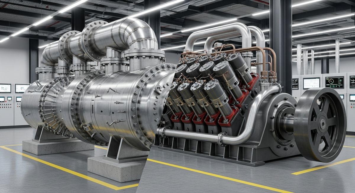
In my 20 plus years of designing piping systems and specifying rotating equipment for heavy petrochemical plants, I have seen many projects stumble during the early front-end engineering design (FEED) phase simply because the wrong compressor technology was selected. Deciding between a centrifugal and a reciprocating compressor is not just a matter of comparing initial purchase costs. It is a fundamental decision that shapes your entire facility’s piping layout, pulsation dampening requirements, maintenance schedules, and electrical substation sizing.
When you are dealing with high-volume, continuous processes like ethylene production or main gas transmission lines, the dynamic nature of a centrifugal compressor is almost always the default choice. However, when your process demands extremely high compression ratios, handles low molecular weight gases at modest flow rates, or requires frequent start-stop cycles, the positive displacement mechanism of a reciprocating machine becomes indispensable. Let us dive deep into the physics, the mechanical realities, and the operational trade-offs of these two industrial workhorses.
Key Engineering Takeaways
- Flow vs. Pressure: Centrifugal compressors excel at high flow rates and low-to-medium pressure ratios, whereas reciprocating compressors are designed for low-to-medium flow rates and extremely high pressure ratios.
- Pulsation and Vibration: Reciprocating units generate severe cyclic pressure pulsations requiring robust dampeners designed per API 618, while centrifugal units deliver smooth, continuous flow.
- Turndown and Flexibility: Reciprocating compressors offer superior part-load efficiency through clearance pockets and valve lifters, whereas centrifugal units are limited by surge and stonewall limits.
- Maintenance Footprint: Centrifugal machines run continuously for years with minimal intervention, while reciprocating units require regular valve, piston ring, and packing replacements.
Analyzing Centrifugal vs Reciprocating Compressor Performance
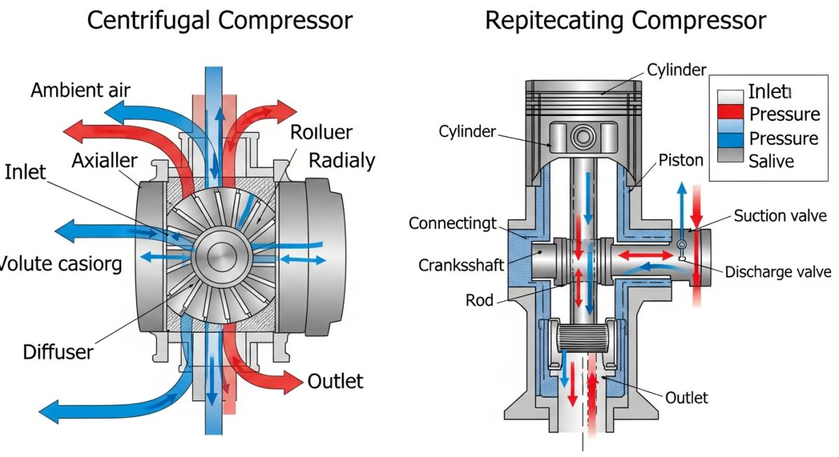
To truly understand these machines, we must look at how they transfer energy to the gas. A centrifugal compressor is a dynamic machine. It uses a high-speed rotating impeller to accelerate the gas molecules, converting mechanical energy into kinetic energy. This high-velocity gas then passes through a diffuser, where the velocity decreases and the kinetic energy converts into static pressure. This process is governed by the polytropic head equation:
Where Hp is the polytropic head, Z is the average gas compressibility factor, R is the specific gas constant, T1 is the suction temperature, P1 and P2 are the suction and discharge pressures, and n is the polytropic exponent. Because the head developed is a function of gas velocity, any change in gas molecular weight directly impacts the discharge pressure. If the gas gets lighter, the developed pressure ratio drops significantly.
Conversely, a reciprocating compressor is a positive displacement machine. It traps a specific volume of gas in a cylinder and physically reduces that volume using a moving piston. This action increases the pressure of the gas until it exceeds the discharge line pressure, forcing the discharge valves open. The volumetric efficiency of a reciprocating compressor is expressed as:
Where VE is the volumetric efficiency, C is the cylinder clearance volume percentage, k is the isentropic exponent of the gas, and L represents internal leakage losses. Because it physically squeezes the gas, a reciprocating compressor will deliver virtually the same discharge pressure regardless of the gas molecular weight, making it highly versatile for varying gas compositions.
In my years on site, I have witnessed catastrophic impeller failures due to surge. Centrifugal compressors have a minimum flow limit (surge point) below which the gas flows backward through the impeller, causing violent pressure oscillations and shaft vibrations. Reciprocating compressors do not suffer from surge, but they are strictly limited by rod load limits (both tension and compression) and gas discharge temperatures, which must never exceed 150 degrees Celsius (300 degrees Fahrenheit) per API 618 to prevent cylinder lubricant degradation and ring wear.
Mechanical Stress and Piping Design Implications
The mechanical differences dictate how we design the surrounding piping systems. Centrifugal compressors run at high speeds (often 5,000 to 20,000 RPM) and require high-precision hydrodynamic bearings, dry gas seals, and sophisticated lube oil consoles designed to API 614. The piping must be designed with minimal nozzle loads to prevent casing distortion, which can cause shaft misalignment.
Reciprocating compressors run at much lower speeds (typically 300 to 1,200 RPM) but generate massive, low-frequency unbalanced forces. The reciprocating motion of the pistons, crossheads, and connecting rods creates primary and secondary unbalanced forces that are transmitted directly to the foundation. Furthermore, the intermittent flow creates severe pressure pulsations in the piping. Without pulsation dampening bottles designed to API 618 Acoustic Simulation standards, these pulsations will cause fatigue failure at small-bore piping connections, instrument taps, and pipe supports.
Comparing Technical Parameters and Operating Limits
The table below outlines the typical operating envelopes and mechanical characteristics of both compressor types. These values represent standard industrial designs, though specialized engineered-to-order machines can exceed these boundaries.
| Parameter | Centrifugal Compressor (API 617) | Reciprocating Compressor (API 618) |
|---|---|---|
| Flow Capacity Range | Very High (1,000 to 500,000 m³/hr) | Low to Medium (50 to 15,000 m³/hr) |
| Maximum Discharge Pressure | Up to 350 bar (Special designs up to 700 bar) | Extremely High (Up to 3,000 bar in hyper-compressors) |
| Pressure Ratio per Stage | Low (1.2 to 2.0) | High (2.0 to 4.5) |
| Flow Characteristic | Continuous, pulse-free flow | Pulsating, cyclic flow |
| Part-Load Efficiency | Poor (Efficiency drops rapidly off-design) | Excellent (Maintained via step-less unloading) |
| Sensitivity to Gas Composition | High (Changes in MW alter head and surge limits) | Low (Handles varying MW and liquid traces better) |
| Typical Maintenance Interval | 3 to 5 years continuous operation | 8,000 to 12,000 operating hours |
| Foundation Requirements | Standard structural steel or concrete table | Massive concrete block anchored to bedrock |
Technical Mapping & Specifications Matrix
To assist piping and mechanical engineers in specifying auxiliary systems, the following matrix maps the core technical entities, standards, and critical failure modes associated with each compressor class.
| Technical Entity | Centrifugal Systems | Reciprocating Systems |
|---|---|---|
| Governing Design Standard | API Standard 617 | API Standard 618 |
| Primary Stress Parameter | Torsional vibration, lateral rotor dynamics | Frame load, rod reversal, piping pulsation |
| Capacity Control Method | Inlet guide vanes, speed control, recycle valve | Clearance pockets, suction valve unloaders |
| Common Failure Mode | Impeller erosion, dry gas seal contamination | Valve fatigue, piston ring wear, packing leaks |
| Lubrication System | Hydrodynamic bearing oil loop (API 614) | Frame lube oil plus high-pressure cylinder injection |
How to Select the Right Compressor
When you are tasked with selecting a compressor for a new process unit, you cannot rely on guesswork. You need a structured verification process. Below is the exact checklist I use during the FEED phase to evaluate process requirements and ensure the selected compressor type aligns with long-term reliability goals.
FEED Phase Compressor Selection Checklist
-
Define the Process Envelope: Establish the absolute minimum, normal, and maximum flow rates. If the flow turndown requirement is greater than 30% from design, a reciprocating compressor or a multi-unit centrifugal configuration is required.
-
Analyze Gas Composition and Molecular Weight: Determine if the gas molecular weight is constant or variable. For highly variable gases (e.g., flare gas recovery), a reciprocating compressor is preferred because its head capacity is independent of molecular weight.
-
Calculate the Total Pressure Ratio: If the required discharge pressure is extremely high (above 150 bar) and the flow rate is low, a multi-stage reciprocating compressor is thermodynamically more efficient and mechanically feasible.
-
Evaluate Footprint and Foundation Constraints: Assess the site soil conditions. Reciprocating compressors require massive concrete foundations and piling to absorb dynamic forces. If the unit is located on an offshore platform or a raised structural mezzanine, a centrifugal compressor is highly preferred.
-
Assess Utility and Maintenance Infrastructure: Verify if the plant has the maintenance capability to service reciprocating valves and packing every 12 months. If the plant is in a remote location with minimal staff, a centrifugal compressor with a 5-year run-time is the safer choice.
Field Case Study: Centrifugal vs Reciprocating Compressor Selection
During a major hydrocracker expansion project at a refinery in the Middle East, our engineering team faced a critical decision. We needed to specify a hydrogen make-up compressor. The process required compressing 98% pure hydrogen gas from an inlet pressure of 25 bar to a discharge pressure of 145 bar. The normal flow rate was 12,000 normal cubic meters per hour (Nm³/hr), but the process required the compressor to operate efficiently down to 4,000 Nm³/hr during catalyst regeneration phases.
The Engineering Dilemma
The initial FEED package proposed a multi-stage centrifugal compressor because of its compact footprint and high reliability. However, during detailed engineering, we realized that because hydrogen has an extremely low molecular weight (MW = 2.016), a centrifugal compressor would require at least 12 to 14 impellers split across two casings to generate the required polytropic head. This would lead to an incredibly complex rotor dynamic design, high risk of shaft instability, and very high power consumption due to windage losses.
The Technical Solution and Outcome
I led the team to perform a comprehensive lifecycle cost analysis comparing the centrifugal option with a 3-stage, 4-throw reciprocating compressor designed to API 618. The reciprocating compressor handled the low molecular weight hydrogen with ease, requiring only three stages of compression. To handle the wide turndown requirement (from 12,000 down to 4,000 Nm³/hr), we specified step-less capacity control using hydraulic suction valve unloaders. This allowed the compressor to match the process demand precisely, saving over 1.2 Megawatts of electrical power during low-flow operations.
Although the reciprocating compressor required a much larger foundation, extensive pulsation dampening bottles, and a comprehensive acoustic study, the overall capital expenditure was 25% lower than the multi-casing centrifugal option. More importantly, the operating energy savings paid back the additional maintenance costs of the reciprocating valves within the first 18 months of operation. This project proved that for low molecular weight gases at high pressures, positive displacement technology remains the superior engineering choice.
Frequently Asked Engineering Questions
Why does gas molecular weight affect centrifugal compressors but not reciprocating compressors?
What is the typical limit for discharge temperature in reciprocating compressors?
How do you control the capacity of a centrifugal compressor?
What are the main causes of vibration in reciprocating compressor piping?
Which compressor type is more efficient at full load?
Can centrifugal compressors handle liquid carryover?
Complete Course on
Piping Engineering
Check Now
Key Features
- 125+ Hours Content
- 500+ Recorded Lectures
- 20+ Years Exp.
- Lifetime Access
Coverage
- Codes & Standards
- Layouts & Design
- Material Eng.
- Stress Analysis

📚 Recommended Resources: centrifugal vs reciprocating compressor
Read these Guides


Related posts:
![A mechanical sucker rod pumpjack operating in an oil field at sunset]()
What is Sucker Rod Pump System in Oil Production?
![Piping material engineer reviewing technical specifications on a tablet in an industrial plant.]()
How a Piping Material Engineer Drives Industrial Project Success
![Industrial refinery plant showing various types of static equipment]()
What is Static Equipment? Types and List of Static Equipments
![Side-by-side comparison of industrial process piping and power plant steam piping systems.]()
Differences Between ASME B31.3 and B31.1: B31.3 vs B31.1
![Large industrial steel storage tank under construction with cranes and scaffolding]()
Storage Tank Construction Method Statement: Step-by-Step Engineering Guide
![Cutaway diagram of a globe control valve highlighting the internal valve trim components]()
What is a Valve Trim? Types, Components, and Selection


