Casting vs Forging: Key Differences for Industrial Piping Systems
In my 20+ years of piping engineering, I have stood on active refinery floors where a single component failure brought down an entire process unit. More often than not, the root cause traced back to an incorrect material forming specification. Choosing between a cast and a forged component is not merely a matter of comparing price tags; it is a fundamental decision that dictates how your piping system will behave under extreme pressure, thermal shock, and cyclic loading.
When we design systems under ASME B31.3, we must account for the inherent physical differences that casting and forging introduce into the metal’s grain structure. A cast valve body and a forged valve body might look identical on an isometric drawing, but under the microscope and under pressure, they are entirely different beasts.
Key Engineering Takeaways
- Structural Integrity: Forgings offer superior directional strength and fatigue resistance due to continuous grain flow.
- Design Flexibility: Castings excel at producing complex, hollow geometries and large-scale components that are economically unfeasible to forge.
- Quality Factors: ASME codes penalize castings with a quality factor (typically 0.80) unless rigorous non-destructive examination (NDE) is performed.
- Cost Dynamics: Forging requires high tooling costs, making it ideal for high-volume or critical-service runs, while casting is highly cost-effective for low-volume, intricate shapes.
Mechanical Integrity of Casting vs Forging Components
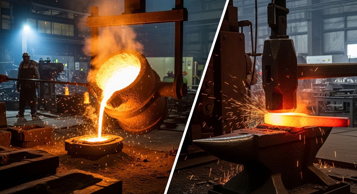
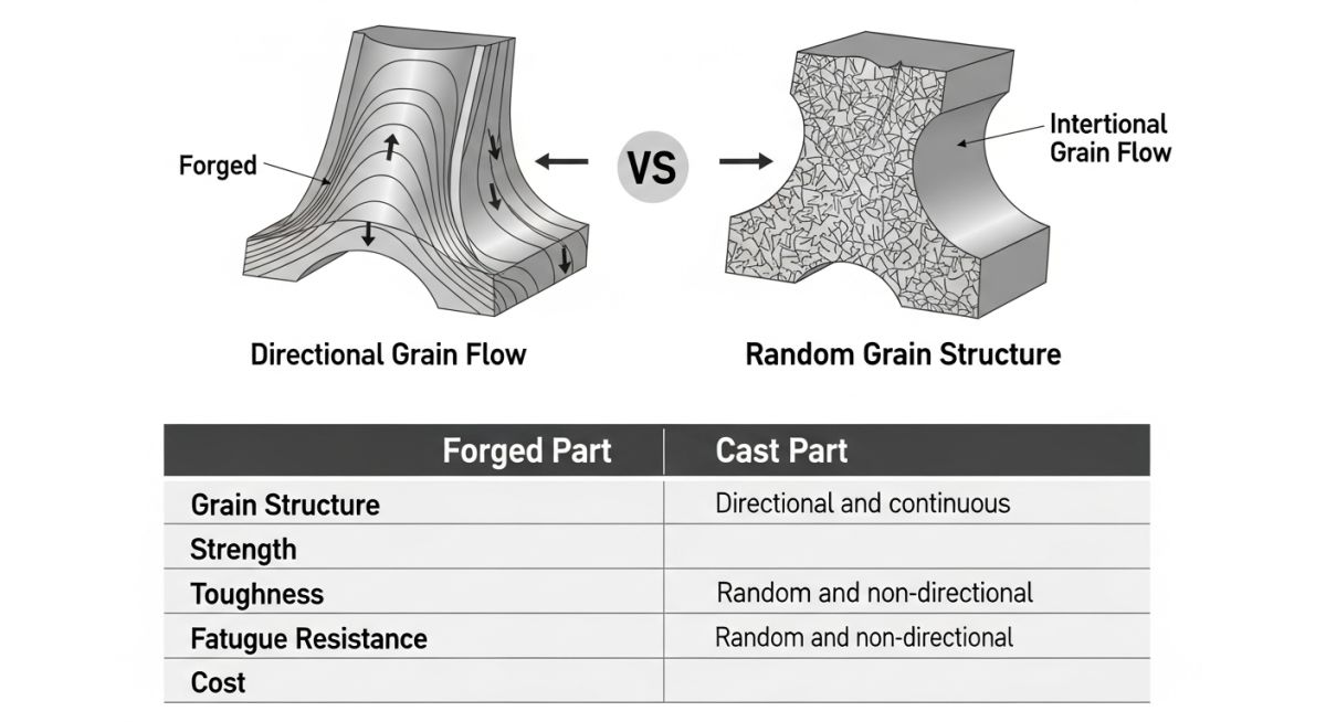
To truly understand the debate of casting vs forging, we must look at the grain structure. When metal is cast, it is heated past its melting point and poured into a mold. As it cools, the crystals grow dendritic structures in a random, isotropic pattern. While this uniform orientation means the material properties are relatively equal in all directions, it also leaves the component vulnerable to internal shrinkage, gas porosity, and dendritic segregation.
Forging, on the other hand, takes a solid billet and deforms it plastically under immense pressure using hammers or presses. This process does not melt the metal; instead, it refines the existing grain structure, aligning the grains along the physical contours of the part. This continuous, directional grain flow yields exceptional tensile strength, impact toughness, and fatigue resistance along the primary loading axes.
ASME B31.3 Wall Thickness Calculations
Let us look at how this structural difference directly impacts our engineering calculations. Under ASME B31.3 Section 304.1.2, the minimum required wall thickness (t) for a straight pipe or cylindrical component under internal pressure is calculated using the following formula:
Where:
- P: Internal design gage pressure (psi)
- D: Outside diameter of the component (inches)
- S: Allowable stress value for the material at design temperature (psi)
- E: Quality factor (Ec for castings, Ef for forgings)
- W: Weld joint strength reduction factor (typically 1.0)
- Y: Coefficient from Table 304.1.1 (typically 0.4 for ferritic steels below 900°F)
Real-World Calculation Comparison:
Consider an 8-inch Nominal Pipe Size (NPS) bypass line operating at a design pressure (P) of 600 psi and a design temperature of 200°F. The outside diameter (D) is 8.625 inches. We are comparing a cast carbon steel valve body (ASTM A216 Grade WCB) against a forged carbon steel valve body (ASTM A105).
From ASME B31.3 Table A-1, the allowable stress (S) for both materials at 200°F is 20,000 psi. However, the quality factor (E) differs significantly:
- For the forged ASTM A105 component, the quality factor Ef = 1.00.
- For the cast ASTM A216 WCB component, without additional non-destructive examination, the casting quality factor Ec = 0.80 (per Table 302.3.3b).
Forged Component (ASTM A105)
t = (600 * 8.625) / (2 * (20,000 * 1.00 * 1.0 + 600 * 0.4))
t = 5175 / (2 * (20,000 + 240))
t = 5175 / 40,480
t = 0.128 inches
Cast Component (ASTM A216 WCB)
t = (600 * 8.625) / (2 * (20,000 * 0.80 * 1.0 + 600 * 0.4))
t = 5175 / (2 * (16,000 + 240))
t = 5175 / 32,480
t = 0.159 inches
This calculation reveals that the cast component requires a 24.2% thicker wall than the forged component to handle the exact same process conditions. This thickness penalty translates directly to increased component weight, larger space envelopes, and higher structural support requirements on your pipe racks.
In my field audits, I often find engineers trying to save money by purchasing cheap cast valves without realizing that the standard casting quality factor of 0.80 applies. To raise this factor to 1.00, you must perform 100% radiography (RT) or ultrasonic testing (UT) on all pressure-retaining areas in accordance with ASME B16.34. The cost of this NDE often completely wipes out any initial savings over a forged alternative.
To assist in your material selection process, the table below outlines the mechanical property differences between common cast and forged equivalents used in high-pressure piping systems.
| Property / Parameter | Cast Carbon Steel (ASTM A216 WCB) | Forged Carbon Steel (ASTM A105) | Cast Stainless Steel (ASTM A351 CF8M) | Forged Stainless Steel (ASTM A182 F316) |
|---|---|---|---|---|
| Minimum Tensile Strength | 70 ksi (485 MPa) | 70 ksi (485 MPa) | 70 ksi (485 MPa) | 75 ksi (515 MPa) |
| Minimum Yield Strength | 36 ksi (250 MPa) | 36 ksi (250 MPa) | 30 ksi (205 MPa) | 30 ksi (205 MPa) |
| Minimum Elongation (2 in.) | 22% | 22% | 30% | 30% |
| Fatigue Resistance | Moderate (Isotropic) | High (Anisotropic) | Moderate | Very High |
| Impact Toughness (Charpy V-Notch) | Variable (Subject to voids) | Excellent (Refined grain) | Good | Outstanding |
Technical Mapping & Specifications Matrix
The following matrix maps the core technical entities, structural acronyms, and physical parameters to their respective design standards.
| Manufacturing Process | Primary ASME/ASTM Codes | Common NDE Methods | Typical Defects | Optimal Applications |
|---|---|---|---|---|
| Metal Casting | ASME B16.34, ASTM A216, ASTM A351 | RT (Radiography), UT (Ultrasonic), PT (Dye Penetrant) | Porosity, Shrinkage cavities, Sand inclusions, Hot tears | Complex valve bodies, large pump casings, low-pressure fittings |
| Metal Forging | ASME B16.5, ASTM A105, ASTM A182 | UT (Ultrasonic), MT (Magnetic Particle), PT | Laps, Seams, Cold shuts, Internal bursts | High-pressure flanges, small-bore valves, critical manifolds |
Site Inspection Checklist for Castings and Forgings
Before any valve, flange, or fitting is welded into a piping spool, the field quality control team must verify its manufacturing pedigree. Use this checklist on-site to prevent catastrophic material mix-ups.
Field QA/QC Verification Steps
-
MTR Verification: Cross-reference the heat number stamped on the component body with the Mill Test Report (MTR). Verify chemical composition and mechanical properties meet the specified ASTM standard.
-
Visual Surface Inspection (MSS SP-55): For cast components, inspect the surface finish against MSS SP-55 quality standards. Check for visible sand inclusions, scabs, or hot tears.
-
NDE Endorsement Check: Ensure that cast valves in high-pressure or lethal service have documentation proving they underwent RT or UT to justify a quality factor of 1.00 under ASME B31.3.
-
Dimensional Tolerances: Measure critical dimensions (face-to-face, flange thickness, bolt hole alignment) to ensure compliance with ASME B16.5 (forged flanges) or ASME B16.34 (valves).
-
Hardness Testing: For forged components in sour service (NACE MR0175/ISO 15156), verify that the field hardness testing does not exceed 22 HRC to prevent sulfide stress cracking.
Field Case Study: Real-World Application
The Problem: Fatigue Cracking in Cast Valve Bodies
At a natural gas processing plant in Alberta, Canada, a series of 3-inch Class 600 control bypass valves experienced repeated body cracking within 14 months of commissioning. The process fluid was high-pressure hydrocarbon gas subject to severe pressure pulsations and mechanical vibration from adjacent reciprocating compressors.
The original specification allowed the use of cast ASTM A216 WCB valve bodies. Metallurgical analysis of the failed valves revealed micro-porosity at the junction of the valve neck and body. These tiny casting voids acted as stress concentration points, initiating fatigue cracks under the cyclic loading of the compressor pulsations.
The Outcome: Upgrading to Forged Integrity
As the lead piping consultant, I recommended replacing the cast valves with forged ASTM A105 valve bodies. The forged bodies possessed a refined, continuous grain flow that naturally wrapped around the valve neck transition, eliminating the stress concentration zones.
Additionally, the forged valves provided a 100% quality factor without requiring the expensive, continuous radiographic monitoring that the castings demanded. Following the installation of the forged valves, the bypass line has operated for over six years without a single recorded crack or pressure drop incident.
Direct Recommendation: For any piping system operating near reciprocating machinery, high cyclic thermal stresses, or severe water hammer potential, always default to forged components. The isotropic nature of castings makes them highly susceptible to rapid fatigue propagation when internal micro-voids are present.
Resolving Common Casting vs Forging Engineering Queries
Why does ASME B31.3 penalize cast components with a 0.80 quality factor?
Can a forged component be welded directly to a cast component?
Which process is more cost-effective for custom, low-volume piping components?
How does grain flow affect the directional strength of forgings?
What is the maximum temperature limit difference between cast and forged stainless steel?
How do I identify if an installed valve is cast or forged?
Complete Course on
Piping Engineering
Check Now
Key Features
- 125+ Hours Content
- 500+ Recorded Lectures
- 20+ Years Exp.
- Lifetime Access
Coverage
- Codes & Standards
- Layouts & Design
- Material Eng.
- Stress Analysis


