
What is Brinell Hardness Test? Procedure, Formula, Standards
In my 20 years of managing piping integrity and material selection for high-pressure petrochemical plants, I have seen many material failures that could have been avoided with proper hardness testing. When dealing with heavy-walled castings, forged flanges, or large structural steel components, the Brinell hardness test is my absolute go-to method. Unlike other micro-hardness tests, it provides a highly reliable bulk measurement that averages out localized microstructural variations.
If you are specifying materials for high-stress applications, understanding how this test is executed, how the formula works, and how to interpret the standards is not just academic knowledge—it is a fundamental requirement for plant safety and structural reliability. Let us break down the mechanics, the mathematics, and the field realities of this indispensable metallurgical tool.
Key Takeaways for Piping & Materials Engineers
- The test uses a 10 mm tungsten carbide ball as the standard indenter to distribute force over a wide area.
- It is highly suited for coarse-grained materials like cast iron and heavy forgings where micro-indentation tests fail to represent bulk properties.
- Test results are designated by the letters HBW, indicating the use of a tungsten carbide (Wolfram) ball.
- Specimen thickness must be at least ten times the depth of the indentation to prevent anvil interference.
- The test must comply strictly with ASTM E10 or ISO 6506-1 protocols to be legally and technically valid.
Why Use the Brinell Hardness Test?
When I evaluate a large forged flange or a heavy-walled valve body, I cannot rely on micro-hardness tests like Vickers or Rockwell. Those methods use tiny indenters that might land directly on a single hard carbide precipitate or a soft ferrite grain, yielding highly localized and unrepresentative readings. The Brinell test solves this by using a large tungsten carbide ball, typically 10 millimeters in diameter, pressed under a heavy load of up to 3000 kilograms-force.
This massive indenter deforms a relatively large volume of material. The resulting impression averages out the microstructural variations, giving us a true representation of the bulk material hardness. This is why international standards like ASTM E10 and ISO 6506-1 mandate this test for heavy industrial components.
The Mathematical Formula
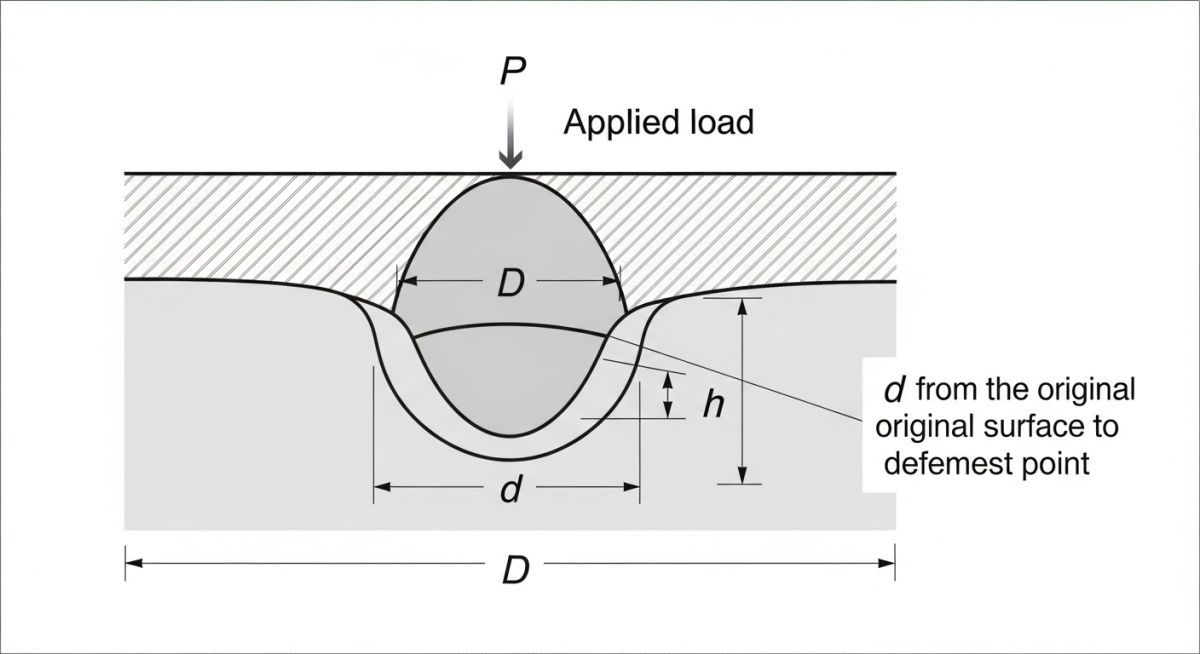
The Brinell Hardness Number (HBW) is calculated by dividing the applied load by the surface area of the resulting curved indentation. The formula is written as follows:
Where:
- P = Applied load in kilograms-force (kgf)
- D = Diameter of the tungsten carbide ball indenter in millimeters (mm)
- d = Mean diameter of the indentation in millimeters (mm), which is the average of two perpendicular measurements
- pi = Mathematical constant approximately equal to 3.14159
In modern laboratories, the testing machine is integrated with an optical system that automatically measures the indentation diameter and calculates the HBW value. However, as a field engineer, I always double-check the raw measurements. If your optical reading of the indentation diameter is off by even 0.1 millimeters, it can lead to a significant error in your calculated hardness value, potentially leading to the acceptance of a non-compliant, brittle component.
Never perform a test too close to the edge of a specimen or on a piece that is too thin. ASTM E10 states that the center of the indentation must be at least 2.5 times the indentation diameter away from any edge. The thickness of the specimen must be at least 10 times the depth of the indentation. If you violate these rules, the material will flow outward or the anvil will support the load, rendering your test data completely useless.
Understanding the HBW Designation
You will often see hardness specified as “250 HBW 10/3000”. This is not random code; it contains all the test parameters. The “250” is the hardness value. “HBW” indicates Hardness Brinell Wolfram (tungsten carbide). The “10” represents the indenter ball diameter in millimeters, and “3000” represents the applied load in kilograms-force. If the dwell time differs from the standard 10 to 15 seconds, it is appended at the end (e.g., 250 HBW 10/3000/30 for a 30-second dwell).
Standard Parameters for Brinell Hardness Test
To maintain geometric similarity across different tests, the ratio of the applied force to the square of the ball diameter must be kept constant for a given material class. This is known as the force-diameter ratio. The table below outlines the standard combinations used in industrial metallurgy.
| Material Group | Typical Hardness (HBW) | Ball Diameter D (mm) | Applied Load P (kgf) | Force-Diameter Ratio (P/D²) |
|---|---|---|---|---|
| Carbon Steel & Cast Iron | 140 to 650 | 10 | 3000 | 30 |
| Copper Alloys & Bronze | 50 to 200 | 10 | 1000 | 10 |
| Aluminum Alloys | 15 to 100 | 10 | 500 | 5 |
| Soft Lead & Tin Alloys | 3 to 15 | 10 | 100 | 1 |
Technical Mapping & Specifications Matrix
The following matrix maps the core technical entities, structural acronyms, and physical parameters associated with hardness testing under international codes.
| Entity / Acronym | Technical Definition | Standard Reference | Engineering Application |
|---|---|---|---|
| HBW | Hardness Brinell Wolfram (Tungsten Carbide ball indenter) | ASTM E10 | Standard designation for Brinell hardness values across all modern engineering materials. |
| HBS | Hardness Brinell Steel (Steel ball indenter) | Obsolete (ASTM E10) | Older designation, no longer permitted for materials with hardness exceeding 350 HBW due to ball deformation. |
| Force-Diameter Ratio | The ratio of applied force to the square of the ball diameter (P/D²) | ISO 6506-1 | Used to maintain geometric similarity when testing with smaller ball diameters (e.g., 5mm or 2.5mm). |
| Dwell Time | The duration for which the full test force is applied to the specimen | ASTM E10 Section 7.3 | Typically 10 to 15 seconds for steel, up to 30 seconds for softer, creep-prone metals. |
How to Perform Brinell Hardness Test
Executing a hardness test in the field requires meticulous attention to detail. Any shortcut taken during surface preparation or machine calibration will directly compromise the integrity of your data. I have developed this checklist over years of conducting field inspections to ensure my team never misses a step.
Field Inspection & Execution Checklist
-
Surface Preparation: Grind the test surface to a smooth, flat finish (minimum 240 grit) to remove scale, decarburized layers, and surface roughness. The surface must be free of oil, grease, and paint. -
Specimen Thickness Verification: Confirm that the specimen thickness is at least 10 times the expected indentation depth. If testing a pipe wall, verify the wall thickness meets this criterion. -
Edge Distance Compliance: Ensure the center of the indentation is located at least 2.5 times the indenter diameter away from any edge or previous indentation. -
Indenter Inspection: Inspect the tungsten carbide ball for flat spots, cracks, or contamination. Replace the ball immediately if any defects are visible under magnification. -
Load Application: Apply the load smoothly without shock or vibration. Maintain the full load for 10 to 15 seconds for steel, or up to 30 seconds for softer alloys. -
Optical Measurement: Measure the indentation diameter in two perpendicular directions using a calibrated optical micrometer. The difference between the two readings must not exceed 2% of the mean diameter. -
Calibration Verification: Perform a daily verification test on a certified reference block close to the expected hardness range of your test material.
Field Case Study: Real-World Application
During a hydrotest at a major refinery expansion project, a heavy-walled ASTM A216 WCB carbon steel gate valve body developed a through-wall crack. The valve had undergone extensive weld repairs during manufacturing. I suspected that the post-weld heat treatment (PWHT) was either skipped or performed incorrectly, leaving localized hard zones that were highly susceptible to hydrogen-induced cracking and brittle fracture.
We deployed a portable Brinell hardness tester to the site. After grinding the surface to a mirror finish, we took readings across the heat-affected zone (HAZ) of the weld repair. The readings came back at 245 HBW. The maximum allowable hardness for this service under NACE MR0175 is 200 HBW. This confirmed our suspicion of improper PWHT.
We rejected the valve, ordered a localized stress-relief heat treatment, and re-tested. The post-heat-treatment hardness dropped to a safe 185 HBW, and the valve successfully passed the subsequent hydrotest.
This case highlights why I insist on physical hardness testing rather than relying solely on paper mill test certificates. Paper can be forged or misfiled, but the physical indentation left by a tungsten carbide ball never lies.
Frequently Asked Engineering Questions
What is the difference between HBW and HBS?
Can you convert Brinell hardness to tensile strength?
Why is a 10 mm ball used instead of smaller indenters?
What is the minimum thickness required for a Brinell test?
How does surface roughness affect Brinell test results?
Can Brinell testing be performed on curved surfaces?
Complete Course on
Piping Engineering
Check Now
Key Features
- 125+ Hours Content
- 500+ Recorded Lectures
- 20+ Years Exp.
- Lifetime Access
Coverage
- Codes & Standards
- Layouts & Design
- Material Eng.
- Stress Analysis