Table of Contents

Master Piping Design with Our Caesar II Pipe Stress Analysis Course
In my 20 years of piping engineering, I have seen many young engineers treat Caesar II as a simple data-entry tool. They plug in coordinates, hit run, and assume a green status report means their design is safe. This is a dangerous misconception. A true piping stress engineer must understand the underlying physics, the code requirements, and how the software translates real-world forces into mathematical models. This course is built to bridge that gap, transforming you from a software operator into a highly competent stress analyst.
Throughout my career, I have guided teams through massive refinery expansions and offshore platform designs. The common thread in every successful project is a deep understanding of pipe flexibility. This 30+ hour course is designed to share those hard-earned field insights with you, ensuring you can confidently handle any stress analysis challenge.
Key Course Takeaways
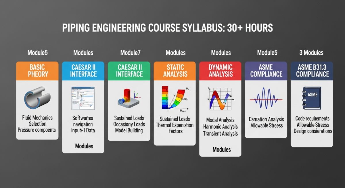
- Master ASME B31.3 and ASME B31.1 code compliance.
- Learn to model complex piping systems, including loops, bypasses, and manifolds.
- Understand how to select, locate, and design piping supports.
- Analyze dynamic loads such as water hammer and relief valve discharge.
- Interpret Caesar II output reports to make safe, cost-effective design modifications.
Complete Course on
Piping Engineering
Check Now
Key Features
- 125+ Hours Content
- 500+ Recorded Lectures
- 20+ Years Exp.
- Lifetime Access
Coverage
- Codes & Standards
- Layouts & Design
- Material Eng.
- Stress Analysis
To truly master piping stress analysis, we must break down the forces acting on a piping system into distinct load cases. In this course, we focus heavily on the three primary load categories defined by the ASME B31.3 code: Sustained, Expansion, and Occasional loads.
1. Sustained Loads (Weight and Pressure)
Sustained loads are constant forces acting on the piping system throughout its operation. These primarily include the weight of the pipe, fittings, insulation, and the fluid inside, along with internal design pressure. The sustained stress (SL) must not exceed the basic allowable stress (Sh) at the design temperature.
Sustained Stress Equation:
SL = (P * D) / (4 * tn) + (0.75 * i * M) / Z <= Sh
Where P is internal design pressure, D is outside diameter, tn is nominal wall thickness, i is the stress intensification factor, M is the sustained bending moment, and Z is the section modulus of the pipe.
2. Expansion Loads (Thermal Displacement)
Thermal expansion occurs when the piping system heats up from its ambient installation temperature to its operating temperature. If the piping is constrained, this expansion generates massive forces and moments. The expansion stress range (SE) is calculated using the displacement stress equation.
Expansion Stress Range Equation:
SE = square root of (Sb squared + 4 * St squared) <= SA
Where Sb is resultant bending stress, St is torsional stress, and SA is the allowable displacement stress range.
3. Occasional Loads (Wind and Seismic)
Occasional loads are temporary forces acting on the system, such as wind, seismic activity, relief valve thrust, or water hammer. ASME B31.3 allows a temporary increase in allowable stress for these short-duration events, typically 1.33 times the basic allowable stress.
| Load Case Type | Primary Drivers | ASME B31.3 Limit | Caesar II Load Case Setup |
|---|---|---|---|
| Sustained (SUS) | Weight, Pressure | Sh (Allowable Stress at Temp) | W + P1 |
| Expansion (EXP) | Thermal Displacement | SA (Allowable Stress Range) | L2 – L1 (Operating – Sustained) |
| Occasional (OCC) | Wind, Earthquake | 1.33 * Sh | W + P1 + WIN or W + P1 + EQ |
| Entity Name | Acronym | Physical Parameter | Caesar II Input Field | Standard Reference |
|---|---|---|---|---|
| Stress Intensification | SIF | Fitting Geometry Factor | SIF & Tees Section | ASME B31.3 Appendix D |
| Modulus of Elasticity | E | Material Stiffness | Elastic Modulus (E) | ASME B31.3 Table C-6 |
| Thermal Expansion | Alpha | Linear Expansion Rate | Thermal Expansion (Alpha) | ASME B31.3 Table C-1 |
Before finalizing any stress analysis report, I always run my team through a strict verification checklist. This ensures that the digital model matches the physical reality of the plant. Skipping these steps can lead to catastrophic failures during commissioning or operation.
Model Validation Checklist
-
Verify that the piping geometry matches the latest Issued for Design (IFD) isometric drawings. -
Confirm that the design temperature and pressure match the process line list. -
Check that the correct material properties and corrosion allowances are assigned. -
Validate support types (guides, anchors, spring hangers) and their friction coefficients. -
Ensure equipment nozzle allowable loads are defined per standard codes like API 610 or API 617. -
Verify that the expansion joint stiffness values match the manufacturer’s data sheets. -
Confirm that all occasional load cases (wind, seismic) are correctly configured per local building codes.
Field Case Study: Real-World Application
The Problem: Turbine Nozzle Overload
During a major refinery turnaround, a newly installed high-pressure steam line was causing severe vibration and alignment issues at the steam turbine inlet. The original design team had run a basic Caesar II analysis but failed to model the actual thermal growth of the turbine casing itself. As a result, the forces on the turbine nozzle exceeded the allowable limits specified by API 617 by over 150%, risking a catastrophic shaft misalignment and bearing failure.
The Solution: Advanced Modeling and Optimization
I was called in to troubleshoot the system. We re-modeled the entire piping run in Caesar II, incorporating the precise thermal displacements of the turbine nozzle. By strategically introducing a 3D expansion loop and replacing two rigid guides with variable spring hangers, we successfully redistributed the thermal expansion forces. The nozzle loads were reduced to 45% of the API 617 limit, completely eliminating the vibration issues during startup.
This case study highlights why deep technical training is so valuable. Our Caesar II pipe stress analysis course teaches you how to handle these exact scenarios, giving you the skills to prevent costly field modifications and operational downtime.
Frequently Asked Engineering Questions
What are the prerequisites for taking this Caesar II course?
How does Caesar II calculate stress intensification factors (SIFs)?
Can I use Caesar II to analyze buried piping systems?
What is the difference between a rigid support and a spring hanger?
How do we handle wind and seismic loads in Caesar II?
Is a certificate provided upon completion of the course?
===

📚 Recommended Resources: Caesar II pipe stress analysis course
Read these Guides
🎓 Advanced Training


Related posts:
![A mechanical sucker rod pumpjack operating in an oil field at sunset]()
What is Sucker Rod Pump System in Oil Production?
![Piping material engineer reviewing technical specifications on a tablet in an industrial plant.]()
How a Piping Material Engineer Drives Industrial Project Success
![Industrial refinery plant showing various types of static equipment]()
What is Static Equipment? Types and List of Static Equipments
![Side-by-side comparison of industrial process piping and power plant steam piping systems.]()
Differences Between ASME B31.3 and B31.1: B31.3 vs B31.1
![Large industrial steel storage tank under construction with cranes and scaffolding]()
Storage Tank Construction Method Statement: Step-by-Step Engineering Guide
![Cutaway diagram of a globe control valve highlighting the internal valve trim components]()
What is a Valve Trim? Types, Components, and Selection


