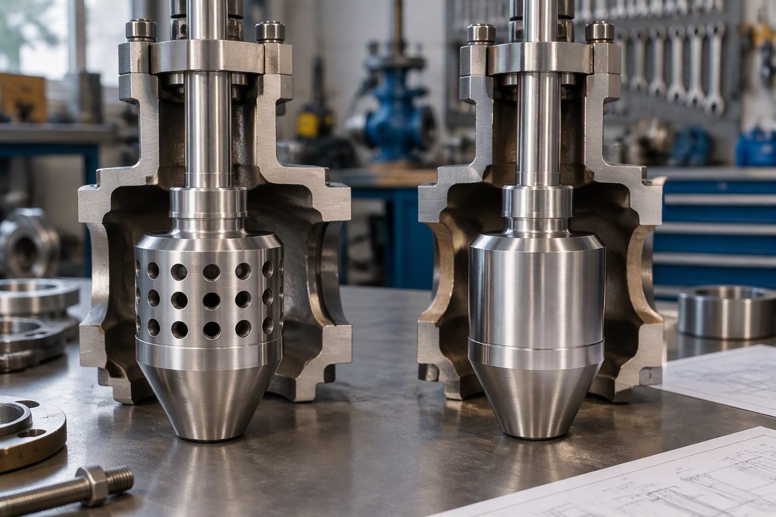
Balanced Control Valve Trim Reduces Actuator Thrust Under High Pressure Drop
In my two decades of reviewing high-pressure piping loops across petrochemical facilities, actuator sizing failures remain a persistent operational bottleneck. When sizing control valves for high-pressure drop services, engineers frequently encounter massive thrust requirements driven by unbalanced plug designs. Without pressure equalization, static fluid forces acting on the seating surface demand oversized pneumatic or electric actuators, escalating capital expenditures and structural weight on the piping rack.
Through my years of commissioning severe service loops, I have observed how adopting balanced control valve trim completely transforms these mechanical dynamics. By drilling precise equalizing holes through the plug body, fluid enters the balancing chamber above the plug, neutralizing downward pressure vectors and optimizing total actuation energy.
Key Engineering Takeaways
- Pressure-equalizing balancing holes neutralize static pressure differentials across the plug face.
- Actuator thrust requirements drop by up to 70 percent in severe pressure drop applications.
- Piston rings and PTFE or graphite seals prevent bypass leakage between the balancing chamber and downstream port.
- Design configurations must strictly satisfy ASME structural wall thickness and leakage class criteria.
Balanced Control Valve Trim Mechanics and Actuator Sizing
When fluid flows through a traditional single-seated globe valve experiencing a high pressure drop, severe static pressure differentials develop across the plug geometry. The resultant hydraulic force acts directly upon the cross-sectional area of the port. Calculating this unbalance force requires evaluating the net differential pressure multiplied by the seat port area. In high-pressure liquid or gas services, this force easily reaches several thousand pounds of thrust, demanding massive spring-diaphragm or piston actuators.
By contrast, a balanced control valve incorporates a cylindrical plug containing internal flow passages or pressure-equalizing holes drilled directly through its body. These holes allow high-pressure fluid from the upstream inlet to enter the balancing cavity situated directly above the plug head. As a result, fluid pressure acts simultaneously on both the top and bottom faces of the plug, effectively canceling out the primary static unbalance vector.
Mathematical Formulation of Actuator Thrust
To accurately specify an actuator for balanced versus unbalanced trims, piping engineers apply standard force-balance equations defined by ASME and ISA standards. The net actuator thrust (F_net) for an unbalanced plug is expressed as:
Where Δ P represents the differential pressure across the valve, A_port is the area of the port, F_seating is the required seat load to achieve tight shutoff, and F_friction accounts for packing box drag. When shifting to a balanced plug design, the pressure-equalizing holes reduce the effective unbalance area to only the cross-sectional area of the stem or the annular clearance gap:
This mathematical reduction transforms the actuation requirement. Because A_stem\_annulus is exponentially smaller than A_port, the primary hydraulic thrust component is virtually eliminated. This enables the use of smaller, lighter actuators that respond faster and consume less instrument air.
Critical Engineering Warning: Bypass Leakage and Seal Failure
While balanced trim drastically reduces actuator thrust, it introduces a secondary sealing interface between the plug body and the cage guide. If the piston ring or dynamic O-ring seal degrades due to chemical attack, high temperature, or particulate abrasion, high-pressure fluid will bypass the plug directly into the balancing chamber.
This bypass flow equalizes pressure across the internal chambers incorrectly, leading to unstable plug positioning, flow-induced vibration, and failure to achieve mandatory FCI 70-2 seat leakage classifications.
Material Selection and Thermal Considerations
Designing balanced trims for severe industrial service requires rigorous attention to metallurgy and thermal expansion coefficients. In high-temperature steam or hydrocarbon processing units operating above 400 degrees Celsius, differential thermal expansion between the plug and the valve cage can cause binding or galling.
Engineers must specify hardened stainless steel alloys, Stellite hardfacing on seating surfaces, and flexible graphite piston rings that maintain dimensional stability under extreme thermal cycling. Adhering to ASTM material specifications ensures that structural integrity remains uncompromised throughout the operational lifecycle of the valve assembly.
Engineering Advantages
- ✓ Reduced Actuator Thrust: Lowers stem force requirements by up to 70%, permitting smaller, lighter pneumatic or electric actuators.
- ✓ Cost Optimization: Eliminates the need for expensive high-pressure hydraulic supply systems and oversized structural mounting brackets.
- ✓ Enhanced Dynamic Response: Smaller actuators exhibit faster stroking speeds and tighter control loop tuning parameters.
- ✓ Extended Component Life: Minimizes stem bending moments and reduces wear on packing box assemblies under high pressure drop.
- ✓ Compliance Ready: Fully aligns with ASME B16.34 pressure-temperature ratings and severe service criteria.
Engineering Disadvantages
- ✗ Seal Wear Vulnerability: Requires dynamic piston rings or O-rings that are susceptible to chemical degradation and abrasive wear.
- ✗ Limited Shutoff Class: Achieving Class VI shutoff is more challenging with balanced trims due to potential bypass leakage past the balancing seal.
- ✗ Particulate Sensitivity: Suspended solids in dirty process fluids can plug balancing holes, causing imbalance failure and erratic control.
- ✗ Higher Initial Complexity: Internal cage guiding and tight machining tolerances increase initial procurement costs over standard unbalanced plugs.
- ✗ Maintenance Overhead: Requires specialized tooling and replacement seal kits during routine plant turnaround overhauls.
High-Pressure Boiler Feedwater Systems
Boiler feedwater control stations operate at extreme pressures, often exceeding 15 megapascals, with substantial pressure drops across the regulating valve. Balanced trim prevents the immense hydraulic forces from locking the valve stem, ensuring smooth modulation and reliable drum level control.
Compliance with ASME Section I standards dictates precise control in these critical power plant loops.
Refinery Hydroprocessing and Hydrocracker Units
Hydrocracker reactor effluent and high-pressure purge gas systems handle severe hydrogen-rich services operating at elevated temperatures. Balanced control valves equipped with specialized graphite seals manage high-pressure drops without requiring prohibitively large piston actuators.
This design satisfies stringent API 560 and API 6D reliability benchmarks for refinery processing environments.
Natural Gas Pipeline Pressure Reduction Stations
City-gate and mainline transmission pressure reduction stations experience large inlet-to-outlet pressure drops that induce severe fluid acceleration and noise. Balanced control trims stabilize plug positioning under these volatile gas expansion conditions, preventing stem chatter and dynamic fatigue.
Engineering practices in these facilities follow rigorous ASME B31.8 gas transmission pipeline safety codes.
Petrochemical High-Pressure Letdown Loops
Ethylene and polyethylene plant letdown valves control high-pressure liquid polymer streams characterized by high viscosity and abrasive catalyst fines. Balanced trim designs incorporate hardened cage guiding to resist erosion-corrosion while maintaining low actuation thrust.
Proper material selection in these units adheres to ASTM metallurgical standards for severe chemical service.
Offshore Subsea Production Choke Valves
Deepwater subsea manifold chokes regulate high-pressure hydrocarbon production streams where space, weight, and actuation power availability are heavily constrained. Balanced trim architectures enable compact electric or hydraulic actuator deployment on seafloor Xmas trees.
Operational reliability in these remote subsea environments complies with ISO 10423 and API 17D specifications.
Balanced Versus Unbalanced Valve Trim Thrust Calculations
Selecting the correct internal trim configuration directly dictates the sizing, capital cost, and dynamic response of your control valve actuation package. When operating under severe pressure drops, unbalanced plugs experience full fluid pressure acting across the entire cross-sectional area of the seating plug, resulting in immense seating and unseating thrust requirements. In my piping design projects across heavy process units, failing to account for this unbalanced force leads to severely oversized pneumatic or electric actuators that strain plant air supplies and degrade control loop tuning.
The following engineering data table contrasts key mechanical performance metrics between traditional unbalanced solid plugs and pressure-equalized balanced plug assemblies designed in accordance with ASME B16.34 and API 598 manufacturing standards. Review these parameters carefully to understand how internal pressure balancing preserves actuator longevity while maintaining tight shutoff capabilities in high-energy service environments.
| Trim Parameter | Unbalanced Solid Plug | Balanced Plug with Equalizing Holes |
|---|---|---|
| Actuator Thrust Force Required | Extremely high; must overcome full delta-P multiplied by port area. | Significantly reduced; pressure equalizes across plug body. |
| Shutoff Class Compliance | Easily achieves FCI 70-2 Class IV, V, or VI with standard soft/metal seats. | Requires specialized piston rings or PTFE seals to maintain Class IV/V shutoff. |
| Maximum Allowable Pressure Drop | Limited by actuator spring range and available supply pressure limits. | Accommodates extreme high delta-P without requiring massive pneumatic cylinders. |
| Maintenance Complexity | Low; simpler internal geometry with fewer dynamic sealing components. | Moderate; requires periodic inspection of balancing seals and equalizing holes. |
Note: Data reflects typical globe-style control valve configurations operating under liquid and compressible gas services. Always verify specific manufacturer sizing software outputs against site operating envelopes.
Technical Mapping & Specifications Matrix
Navigating industrial control valve specification requires a rigorous understanding of the governing codes, physical dimensions, and material classifications that ensure safe mechanical integrity. When designing systems with balanced control valve trim, engineers must map specific operational demands against standardized material test reports and pressure-temperature ratings. This structural alignment prevents catastrophic stem failure and mitigates fluid-induced vibration in high-capacity pipelines.
The matrix below organizes the primary engineering entities, governing industry standards, and structural parameters associated with balanced trim implementation. Each standard is referenced directly to its authoritative body to streamline your quality assurance audits and piping design reviews.
| Engineering Entity | Governing Code / Standard | Technical Description & Function |
|---|---|---|
| Valve Body & Pressure Rating | ASME B16.34 | Defines wall thickness, material groupings, and pressure-temperature ratings for flanged and welded valves. |
| Seat Leakage Classification | FCI 70-2 | Establishes standardized test procedures and allowable leakage rates from Class I through Class VI. |
| Actuator Thrust Calculation | ANSI/ISA-75.01.01 | Provides equations for sizing control valves and calculating hydrodynamic forces acting on valve internals. |
| Valve Inspection & Testing | API 598 | Outlines inspection, examination, and pressure testing requirements for industrial valve manufacturing. |
Ensure all procured valve assemblies include certified material test reports (CMTRs) matching the material group specifications outlined in these standards.
Site Verification Checklist for Balanced Valve Trim Installation
Deploying a balanced control valve assembly in a high-pressure piping circuit demands rigorous pre-commissioning checks to guarantee mechanical reliability and accurate process control. In my field engineering experience, overlooking minor assembly details such as balancing seal orientation or equalizing hole cleanliness can lead to erratic valve positioning and premature wear. Use the structured site verification checklist below during your pre-startup safety reviews (PSSRs) to validate installation compliance against ASME B16.34 guidelines.
Piping and Instrumentation Verification Steps
- Flow Direction Verification: Confirm that the pipeline process flow direction aligns strictly with the valve body directional arrow, ensuring proper upstream pressure application across the equalizing network.
- Balancing Seal Integrity: Inspect the piston ring or elastomer balancing seal for signs of shipping damage, scoring, or improper seating within the plug groove prior to stem connection.
- Equalizing Hole Inspection: Verify that pressure-equalizing drilled holes are completely free of machining burrs, welding slag, or particulate debris that could cause clogging.
- Actuator Thrust Calibration: Calibrate the pneumatic or electric actuator stroke against bench set springs, verifying that available thrust matches maximum expected differential pressure drops.
- Packing Box Torquing: Check packing flange nut torque values to prevent excessive stem friction while maintaining fugitive emission compliance under thermal cycling.
- Hydrostatic Testing Sign-off: Review certified shell and seat hydrostatic test results in accordance with API 598 standards before introducing process fluids.
Completing each verification checkpoint ensures your balanced trim control valve operates smoothly within its design envelope, protecting downstream equipment from instability and minimizing unexpected maintenance shutdowns.
Field Case Study: Resolving Actuator Saturation in High-Pressure Letdown Service
During the commissioning of a high-pressure hydroprocessing unit in a Gulf Coast refinery, our engineering team encountered severe actuator saturation and control loop instability on a primary reactor effluent letdown valve. The 6-inch control valve was originally designed with an unbalanced solid plug to handle a constant differential pressure drop exceeding 4.2 megapascals. Under peak operating conditions, the massive hydrodynamic forces acting on the plug surface overwhelmed the pneumatic diaphragm actuator, causing the valve to stick mid-stroke and inducing severe process oscillations throughout the high-pressure separator loop.
Problem Analysis: Unbalanced Trim Failure Modes
The unbalanced solid plug configuration generated excessive seating and dynamic thrust requirements that exceeded the mechanical limits of the installed actuator package.
- Severe hydrodynamic load caused by full differential pressure acting across the unreduced plug area.
- Actuator spring compression limits reached, resulting in complete loss of throttling control during high-flow surges.
- High stem friction and side-load forces accelerating packing wear and causing visible stem scoring.
- Inability to maintain stable pressure control, triggering frequent high-pressure safety interlock trips.
To resolve this critical operational bottleneck without performing a complete piping redesign or replacing the entire valve body, our team engineered a field retrofit replacing the unbalanced solid plug with a balanced plug assembly featuring precision pressure-equalizing holes drilled directly through the plug body. This modification allowed upstream fluid pressure to enter the cavity above the plug, effectively canceling out the downward net static force while preserving the exterior guiding geometry and flow characteristics.
Case Outcome: Successful Balanced Trim Retrofit
The implementation of pressure-equalized balanced trim successfully stabilized the control loop and restored precise hydraulic regulation across the letdown station.
- Required actuator thrust force reduced by more than 70 percent, eliminating actuator saturation issues.
- Process pressure fluctuations dampened immediately, achieving smooth loop control within tight +/- 1 percent tolerances.
- Eliminated costly piping modifications by utilizing the existing valve body shell in compliance with ASME B16.34 standards.
- Extended preventative maintenance intervals from 6 months to over 3 years of continuous trouble-free operation.
My primary engineering recommendation from this project is to evaluate differential pressure thresholds early during front-end engineering design (FEED). Whenever operating delta-P exceeds 1.5 megapascals in valves larger than 4 inches, specify balanced plug trim with equalizing holes from the outset to avoid costly field retrofits and ensure robust actuator performance.
Frequently Asked Engineering Questions
How does a balanced control valve trim reduce actuator thrust requirements?
- Pressure-equalizing holes create a bypass channel across the plug solid boundary.
- Upstream pressure acts equally on both top and bottom plug cross-sectional areas.
- Actuators only need to overcome spring preload, packing friction, and seat load.
- Thrust capacity requirements drop significantly compared to unbalanced single-seat plugs.
What are the primary leakage rate limitations of balanced trim valves?
- Standard soft-seated balanced plugs can achieve Class VI bubble-tight shutoff.
- Metal-to-metal balanced designs generally achieve Class IV or Class V shutoff.
- Piston ring clearance allows a minimal baseline bypass leakage during closed states.
- Secondary elastomer seals degrade rapidly at extreme cryogenic or high temperatures.
When should an engineer specify unbalanced plugs over balanced trims?
- Small valve sizes (typically below 2 inches) do not benefit from balancing complexity.
- Strict zero-leakage isolation demands metal-seated unbalanced single-port designs.
- Dirty or abrasive fluids can clog pressure-equalizing holes, causing operational failure.
- Simplified mechanical construction reduces maintenance downtime in corrosive services.
How do temperature extremes impact balanced trim piston ring seals?
- PTFE or polymer rings risk extrusion or severe embrittlement outside normal bounds.
- Inconel or graphite piston rings accommodate high-temperature steam up to 550 C.
- Differential thermal expansion can bind the plug inside the valve cage assembly.
- Clearance tolerances must account for material-specific coefficients of expansion.
What maintenance challenges arise with balanced control valve assemblies?
- Piston ring wear leads to internal bypass and loss of effective force balancing.
- Equalizing holes require cleaning to clear accumulated particulate or scale buildup.
- Cage-guided surfaces demand periodic lapping to eliminate galling and scoring marks.
- O-ring and backup ring replacements must be scheduled during standard turnarounds.
- If you are sizing control valves for high-pressure drop hydrocarbon services exceeding 3.0 MPa, specify balanced cage-guided trim to prevent oversized, heavy-actuator configurations that strain structural piping supports.
- When operating dirty or catalyst-laden slurry streams, avoid tight-tolerance balanced plugs with small equalizing holes; instead, opt for robust unbalanced or hardened single-port designs to prevent plugging and catastrophic trim jamming.
- If fugitive emission regulations or tight Class V shutoff requirements apply, ensure your balanced trim selection utilizes metal-backed spring-energized graphite seals rather than standard elastomers to withstand thermal shock and cyclic fatigue.
- When performing annual plant turnarounds, mandate rigorous dimensional inspection of the cage and piston ring clearances against manufacturer tolerances to catch internal bypass wear before it causes severe throttling instability.
Complete Course on
Piping Engineering
Check Now
Key Features
- 125+ Hours Content
- 500+ Recorded Lectures
- 20+ Years Exp.
- Lifetime Access
Coverage
- Codes & Standards
- Layouts & Design
- Material Eng.
- Stress Analysis
