Mastering ASME BPVC Creep Design for High Temperature Vessels
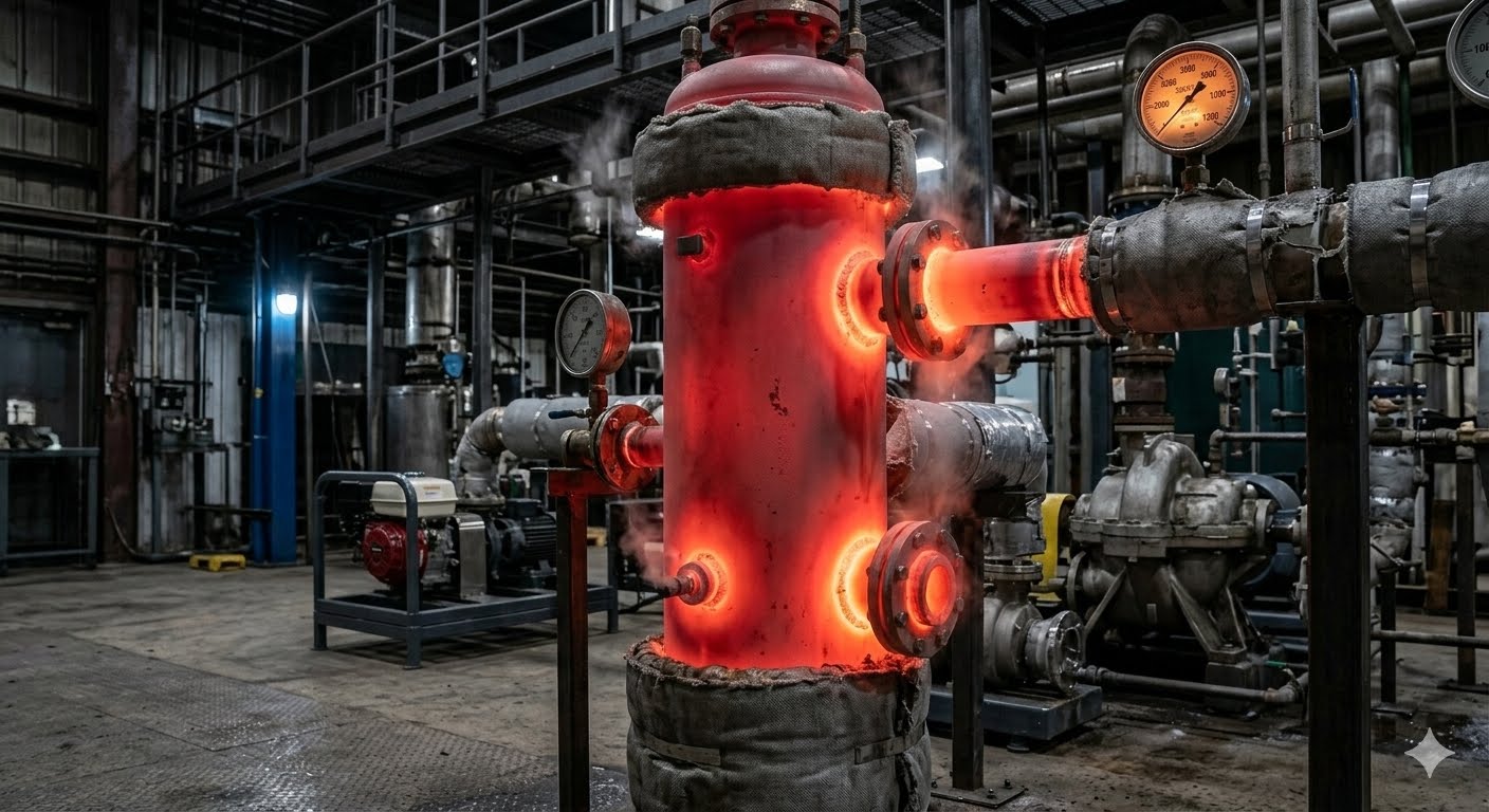
In my 20 plus years of field experience troubleshooting high-temperature piping and pressure vessels, nothing demands respect quite like metal creep. I still vividly recall walking onto a refinery site in 2012 where a superheater header had developed a noticeable sag. The culprit? A minor but sustained operating temperature excursion of just 15 degrees Celsius above the design limit. That field reality drove home a fundamental truth: at elevated temperatures, steel behaves less like a rigid solid and more like an incredibly slow-moving fluid.
Designing systems to withstand this time-dependent plastic deformation requires a deep, practical understanding of the ASME Boiler and Pressure Vessel Code (BPVC). The code does not just give us static stress limits; it provides a comprehensive framework to manage the slow, inevitable degradation of materials over their planned operational lifespans.
Key Engineering Takeaways
- Understand the exact transition temperatures where creep begins to dominate material selection.
- Master the three distinct stages of creep deformation to predict component lifespans accurately.
- Learn how ASME Section II Part D establishes allowable stress limits based on 100,000-hour rupture life.
- Implement robust field inspection protocols to catch micro-cracking before catastrophic failure occurs.
Understanding ASME BPVC Creep Design Rules
Creep Deformation Mechanics: The progressive, time-dependent plastic deformation of metallic materials subjected to constant stress at elevated temperatures, typically starting above forty percent of the absolute melting temperature. This phenomenon requires rigorous stress-rupture analysis and strain-rate evaluation to prevent catastrophic structural failure in high-pressure systems.
To design safe high-temperature components, we must first look at how metals deform over time. When a metal is subjected to a constant load at high temperatures, it undergoes three distinct stages of deformation. I always visualize this using the classic creep curve, which is fundamental to how the ASME BPVC structures its safety margins.
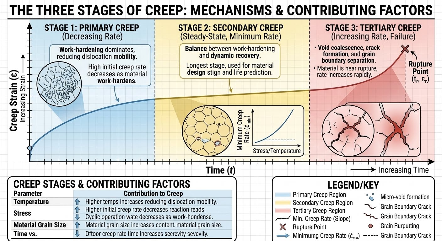
The Three Stages of Creep
1. Primary (Transient) Creep: This is the initial stage where the creep rate starts relatively high but rapidly decreases over time. The material undergoes strain hardening, which increases its resistance to further deformation.
2. Secondary (Steady-State) Creep: In this stage, a delicate balance is reached between strain hardening and thermal recovery. The creep rate remains virtually constant. This is the longest phase of a component’s life, and it is the primary focus of long-term engineering design.
3. Tertiary Creep: This is the dangerous final phase. The creep rate accelerates rapidly due to microstructural damage, such as grain boundary cavitation and void formation. This stage ends in a ductile, high-temperature stress rupture.
In my years on-site, I have seen many operators run systems slightly hotter than design to boost production. Be warned: for most low-alloy steels, a sustained temperature increase of just 10 to 15 degrees Celsius above the design limit can cut the remaining creep life of a component in half. Always design with realistic operating margins.
The Larson-Miller Parameter (LMP)
To predict when a material will transition from steady-state creep to tertiary failure, we rely on the Larson-Miller Parameter. This mathematical relationship allows us to trade time for temperature in laboratory testing, helping us project 100,000-hour lifespans from shorter, high-temperature tests.
LMP = T * (C + log(tr))
Where:
– T is the absolute temperature in Kelvin or Rankine.
– C is a material-specific constant, typically assumed to be 20 for low-alloy and stainless steels.
– tr is the time to rupture in hours.
Practical Calculation Example:
Let us calculate the estimated rupture life of a 2.25Cr-1Mo steel component operating at 540 degrees Celsius (813 Kelvin) under a specific stress level where the material’s LMP is known to be 20,000.
Step 1: Set up the equation:
20,000 = 813 * (20 + log(tr))
Step 2: Divide by the absolute temperature:
24.6 = 20 + log(tr)
Step 3: Isolate the logarithmic term:
log(tr) = 4.6
Step 4: Solve for time (tr):
tr = 10^4.6 = 39,810 hours (approximately 4.5 years of continuous operation).
ASME Section II Part D Allowable Stress Criteria
The ASME Code uses a conservative approach to establish allowable stresses in the creep range. Under ASME Section II Part D, Appendix 1, the allowable stress at any given high temperature is limited to the lowest of the following three values:
- 100% of the average stress to produce a creep rate of 0.01% per 1,000 hours (which equates to 1% deformation over 100,000 hours).
- 67% of the average stress to cause rupture at the end of 100,000 hours.
- 80% of the minimum stress to cause rupture at the end of 100,000 hours.
Applying ASME BPVC Creep Design Limits
High-Temperature Material Limits: The maximum allowable operating temperatures and stress values defined by ASME Section II Part D to prevent premature creep rupture. These limits dictate material selection and wall thickness calculations for components operating in the creep range.
Selecting the right material is the first line of defense against creep. The table below outlines common pressure vessel steels, their creep threshold temperatures, and their primary high-temperature damage mechanisms.
| Material Grade | Nominal Composition | Creep Threshold (°C) | Max Code Temp (°C) | Primary Damage Mechanism |
|---|---|---|---|---|
| SA-516 Gr. 70 | Carbon Steel | 370 | 538 | Graphitization, Spheroidization |
| SA-387 Gr. 11 | 1.25Cr-0.5Mo | 425 | 593 | Temper Embrittlement, Creep Cavitation |
| SA-387 Gr. 22 | 2.25Cr-1Mo | 450 | 649 | Microstructural Coarsening, Creep Rupture |
| SA-335 P91 | 9Cr-1Mo-V | 510 | 649 | Type IV Creep Cracking in HAZ |
| SA-240 Type 304H | 18Cr-8Ni (High Carbon) | 525 | 815 | Sensitization, Sigma Phase Embrittlement |
Technical Mapping & Specifications Matrix
Navigating the different sections of the ASME Code can be challenging. This matrix maps the relevant code sections to their specific roles in high-temperature design.
| ASME Code Section | Core Parameter / Standard | Technical Scope | Reference Link |
|---|---|---|---|
| Section II, Part D | Tables 1A, 1B, and 5A | Provides maximum allowable stress values and physical properties across temperature ranges. | ASME Sec II Part D |
| Section VIII, Div 1 | Subsection C (UCS, UHA) | Defines design rules for carbon, low-alloy, and high-alloy steel vessels operating in the creep range. | ASME Sec VIII Div 1 |
| Section VIII, Div 2 | Part 5 (Design by Analysis) | Provides advanced elastic-plastic analysis rules for high-temperature fatigue and creep-fatigue interaction. | ASME Sec VIII Div 2 |
| API 579-1 / ASME FFS-1 | Part 10 (Creep Assessment) | Establishes fitness-for-service evaluation procedures for equipment found to have active creep damage. | API 579 / ASME FFS-1 |
Field Verification Checklist for Creep
Creep Inspection Protocols: The systematic field verification steps and non-destructive testing methods used to detect early-stage creep void formation and micro-cracking in high-temperature piping and vessels. These procedures ensure compliance with ASME PCC-2 and API 579-1/ASME FFS-1 fitness-for-service assessments.
When I perform a high-temperature system audit, I use a structured checklist to ensure no early signs of creep are missed. This is a practical, field-tested protocol designed to catch damage before it leads to a major failure.
High-Temperature Creep Inspection Protocol
Check DCS logs for any temperature excursions. Note any periods where the system operated above the design temperature specified in the ASME data sheets.
Inspect long piping runs for visible sagging between supports. Measure the outer diameter of high-stress areas to check for localized swelling (diametral strain).
Verify that spring hangers are operating within their design travel range. Bottomed-out or topped-out hangers can introduce massive, unplanned bending stresses that accelerate creep.
Focus on the Heat Affected Zones (HAZ) of dissimilar metal welds. Use advanced techniques like Phased Array Ultrasonic Testing (PAUT) or Time-of-Flight Diffraction (TOFD) to look for subsurface micro-voids.
For critical components nearing their design life, take surface replicas of the metal grain structure. Examine them under a microscope to check for grain boundary cavitation (early-stage creep).
Field Case Study: Real-World Application
Creep Failure Analysis: The forensic engineering evaluation of high-temperature components to identify the root causes of creep-induced deformation and cracking. This process utilizes metallurgical replication and stress analysis to determine remaining useful life.
The Problem: Premature Cracking in Grade 91 Steam Piping
During a planned turnaround at a combined-cycle power plant, inspectors found linear indications in the heat-affected zone (HAZ) of a main steam piping weld. The piping was made of SA-335 P91 steel and operated at 565 degrees Celsius.
The plant had been in service for only 45,000 hours—well short of its 100,000-hour design life. A detailed review of the construction records revealed that the post-weld heat treatment (PWHT) had been poorly controlled, with temperatures occasionally dipping below the code-required minimum. This resulted in a localized, weak microstructure highly susceptible to Type IV creep cracking.
The Outcome: Remediation and Life Extension
To address the issue, we performed in-situ metallurgical replication, which confirmed the presence of advanced creep cavitation along the grain boundaries. We then conducted a Level 2 Fitness-For-Service assessment in accordance with API 579-1/ASME FFS-1.
The damaged weld section was cut out and replaced. We implemented strict, automated temperature controls during the new PWHT to ensure the material reached its optimal tempered martensitic state. In addition, we adjusted the nearby spring hangers to reduce the sustained bending stresses on the joint. These changes successfully restored the system’s structural integrity and secured its long-term operational safety.
Frequently Asked Engineering Questions
Creep Engineering FAQ: A compiled reference addressing critical questions regarding high-temperature material behavior, code compliance, and life assessment methodologies under ASME BPVC.
How does ASME Section II Part D define the threshold temperature where creep design rules govern?
What is the difference between Division 1 and Division 2 of ASME Section VIII regarding high-temperature creep design?
How does the Larson-Miller Parameter help in predicting long-term creep rupture life?
Why is Grade 91 steel highly susceptible to Type IV creep cracking, and how does the code address this?
What non-destructive testing (NDT) methods are recommended for detecting early-stage creep?
How does API 579-1/ASME FFS-1 handle fitness-for-service assessments for components with active creep damage?
===FAQ_BLOCK===

Complete Course on
Piping Engineering
Check Now
Key Features
- 125+ Hours Content
- 500+ Recorded Lectures
- 20+ Years Exp.
- Lifetime Access
Coverage
- Codes & Standards
- Layouts & Design
- Material Eng.
- Stress Analysis