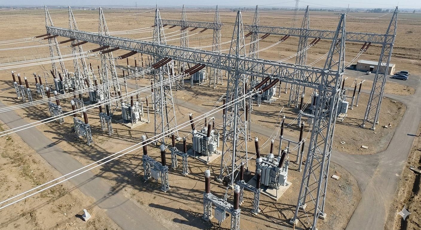
Optimizing Air-Insulated Switchgear Design for Large Scale Substations
In my two decades of experience managing large-scale infrastructure projects, I have found that the design of an Air-Insulated Switchgear (AIS) substation is as much about spatial geometry as it is about electrical capacity. When we lay out a facility on open, flat terrain, we are essentially building a massive, interconnected grid of steel lattice gantry towers and high-voltage conductors.
The primary challenge with AIS is the reliance on atmospheric air as the primary insulating medium. Unlike Gas-Insulated Switchgear (GIS), which allows for a compact footprint, AIS requires generous phase-to-phase and phase-to-ground clearances. This necessity dictates the entire site plan, forcing us to spread equipment bays across vast areas to prevent flashovers and ensure maintenance access.
Key Design Takeaways
- Strict adherence to IEEE 1427 for minimum electrical clearances.
- Strategic gantry tower placement to manage mechanical tension loads.
- Optimized bay spacing to balance land footprint with safety protocols.
- Integration of rigid busbar systems to minimize sag and clearance violations.
Engineering Principles of Air-Insulated Switchgear
Air-Insulated Switchgear design requires rigorous calculation of dielectric clearances and mechanical loading on support structures to maintain system reliability under varying environmental conditions.
When designing an AIS substation, the most critical parameter is the Basic Insulation Level (BIL). We must ensure that the physical distance between energized conductors and grounded structures—or between phases—exceeds the dielectric strength of the air at the site’s specific altitude and humidity levels. As an engineer, I rely on IEEE C37.32 to define these minimum phase-to-ground and phase-to-phase clearances.
The calculation of these clearances is not static. We must account for the “worst-case” scenario, which includes switching surges and lightning impulses. For a 400kV system, for instance, the required clearance is significantly larger than for a 132kV system. If the site is located at a high altitude, the air density decreases, which reduces its dielectric strength. We apply a correction factor to the standard clearance values to compensate for this reduction in insulating capability.
Design Limitation Warning:
Failure to account for altitude-based air density correction factors often leads to unexpected flashovers during transient overvoltage events. Always verify site-specific meteorological data against IEEE 1313.2 before finalizing gantry tower heights.
Gantry tower layout is the next phase of the design. These steel lattice structures serve as the backbone of the substation, supporting the busbars and disconnect switches. We calculate the mechanical tension on these towers by considering the weight of the conductors, wind loading, and ice accumulation. The tension must be balanced across the bay to prevent structural deformation or excessive sag, which could violate the minimum clearance requirements.
In my experience, using rigid busbars instead of flexible conductors in high-current bays can significantly reduce the required footprint. Rigid busbars maintain a constant geometry, allowing for tighter spacing without the risk of conductor swing during high-wind events. However, this requires more robust support insulators and precise alignment of the gantry towers.
We also perform short-circuit force calculations. During a fault, the electromagnetic forces between parallel conductors can be immense. These forces can cause the conductors to whip, potentially leading to a phase-to-phase contact. We design the support insulators and the gantry tower connections to withstand these peak dynamic loads, ensuring the structural integrity of the entire AIS assembly.
AIS Operational Characteristics represent a balance between cost-effective simplicity and the requirement for significant physical space to maintain dielectric safety.
Advantages
- Lower initial capital expenditure compared to GIS.
- High visibility of all components for rapid visual inspection.
- Simplified maintenance procedures due to open accessibility.
- No risk of SF6 gas leakage or environmental compliance issues.
- Easier to expand or modify the substation layout later.
Disadvantages
- Extensive land footprint required for safety clearances.
- Susceptibility to environmental factors like salt, dust, and pollution.
- Higher risk of wildlife-induced outages in open-air designs.
- Increased structural steel requirements for gantry towers.
- Greater exposure to lightning and transient overvoltages.
AIS Deployment Scenarios are best suited for environments where land availability is high and the primary goal is long-term operational transparency and cost efficiency.
Rural Transmission Hubs
In rural areas where land cost is low, AIS is the industry standard for high-voltage transmission hubs. The generous spacing allows for easy integration of multiple incoming and outgoing lines, facilitating complex grid interconnections without the density constraints of urban GIS installations.Large-Scale Renewable Integration
Solar and wind farms often occupy vast, flat tracts of land, making them ideal candidates for AIS substations. The modular nature of AIS allows engineers to scale the substation capacity alongside the growth of the renewable energy facility, providing a cost-effective solution for power evacuation.Industrial Power Distribution
Large industrial complexes, such as refineries or mining operations, utilize AIS to manage high-voltage power distribution across their sites. The ability to perform maintenance on individual bays without de-energizing the entire facility is a critical operational advantage for these continuous-process industries.Designing an Air-Insulated Switchgear (AIS) substation requires strict adherence to phase-to-phase and phase-to-ground clearance distances. These values are dictated by the Basic Insulation Level (BIL) of the equipment and the maximum expected switching surge voltages. In my experience, failing to account for these clearances during the initial site layout phase leads to costly rework when the gantry tower foundations are already poured.
The following table outlines standard minimum clearance requirements based on common voltage levels. These values are derived from IEEE C37.32, which serves as the primary reference for high-voltage switchgear design. Engineers must also consider altitude correction factors, as air density decreases at higher elevations, necessitating larger physical gaps to maintain the same dielectric strength.
| Voltage (kV) | Phase-to-Ground (mm) | Phase-to-Phase (mm) | Sectional Clearance (mm) |
|---|---|---|---|
| 145 | 1300 | 1600 | 3500 |
| 245 | 2100 | 2600 | 5000 |
| 420 | 3600 | 4500 | 8000 |
Always verify these values against your specific project specifications and local environmental conditions. Humidity, pollution levels, and seismic requirements can further influence the final spacing between equipment bays and the structural design of the gantry towers.
The complexity of an AIS substation involves the integration of various electrical, structural, and mechanical entities. Managing these components requires a clear understanding of their functional roles and the standards that govern their performance. This matrix maps the critical entities found in a typical high-voltage AIS installation to their respective design parameters and industry references.
By categorizing these elements, we can better manage the interface between the civil works, such as the gantry tower footings, and the electrical equipment, such as circuit breakers and disconnect switches. This structured approach ensures that all components are compatible with the overall substation layout and safety requirements.
| Entity | Function | Standard Reference |
|---|---|---|
| Gantry Tower | Structural support for busbars | ASCE 113 |
| Circuit Breaker | Fault interruption and switching | IEEE C37.04 |
| Disconnect Switch | Isolation for maintenance | IEEE C37.30 |
| Busbar System | Current distribution path | IEEE 605 |
This matrix serves as a foundational guide for project documentation. When reviewing vendor submittals, I cross-reference the equipment specifications against these standards to ensure the design remains robust and compliant throughout the project lifecycle.
Verification of AIS design parameters is a multi-stage process that begins with site survey data and concludes with final commissioning. In my experience, the most common failures occur due to misaligned gantry tower foundations or insufficient clearance between equipment bays. This checklist provides a systematic approach to verifying your design against IEEE 1427 and other relevant standards.
- 1. Verify that all phase-to-ground clearances meet the minimum BIL requirements for the specific altitude of the site.
- 2. Confirm that gantry tower structural designs account for maximum wind and ice loading as per local building codes.
- 3. Ensure that maintenance access paths between equipment bays are clear of all energized conductors and support structures.
- 4. Validate that the grounding grid design provides adequate step and touch potential protection for all personnel.
- 5. Check that all disconnect switch operating mechanisms are accessible and clear of potential interference from adjacent equipment.
Each item on this list must be signed off by the lead engineer before proceeding to the next phase of construction. Regular site audits are necessary to ensure that the physical installation matches the approved design drawings, especially when dealing with the large-scale footprint of an AIS substation.
The Problem: Unexpected Clearance Violations
During the construction of a 420kV AIS substation, the field team discovered that the installation of a new transformer bay encroached upon the safety clearance of an existing busbar support tower.
- Inaccurate site survey data regarding existing gantry tower locations.
- Failure to account for the swing of flexible busbar conductors during high-wind events.
- Lack of coordination between the civil foundation team and the electrical layout team.
- Inadequate verification of final equipment dimensions against the initial design footprint.
The Outcome: Successful Remediation and Design Optimization
- Implemented a revised busbar tensioning system to reduce conductor swing.
- Installed additional shielding to maintain dielectric integrity within the reduced space.
- Updated the site master plan to include a 3D BIM model for all future bay expansions.
- Achieved full compliance with IEEE safety standards without requiring major structural relocation.
My recommendation for similar projects is to prioritize early-stage 3D modeling and conduct frequent interdisciplinary design reviews. This proactive approach prevents the physical constraints of AIS from becoming a liability during the construction phase.
Why does AIS require such a large physical footprint?
- Higher voltage levels require exponentially larger air gaps to maintain safety.
- Environmental factors like humidity and pollution necessitate even greater clearances.
- The need for maintenance access around each piece of equipment adds to the total area.
How do altitude and air density affect AIS design?
- Standard clearances are typically defined for sea level.
- For sites above 1000 meters, clearances must be increased by a specific percentage per IEEE guidelines.
- Failure to adjust for altitude can lead to unexpected dielectric breakdown during operation.
What are the primary structural loads on gantry towers?
- Dead loads from the weight of the busbars, insulators, and hardware.
- Wind loads acting on the surface area of the conductors and the tower structure itself.
- Ice loading, which significantly increases the weight and surface area of the conductors.
- Short-circuit forces that create intense mechanical stress during fault conditions.
How does AIS compare to GIS in terms of maintenance?
- AIS allows for easier identification of corrosion or mechanical wear.
- GIS requires specialized gas-handling equipment and highly trained personnel for internal maintenance.
- AIS maintenance can often be performed with standard tools, reducing long-term operational costs.
What role does the grounding grid play in AIS safety?
- It provides a low-impedance path for fault currents to return to the source.
- Proper design as per IEEE 80 is essential for personnel safety.
- The grid must be tested periodically to ensure its integrity remains within safe limits.
Are there specific standards for AIS busbar design?
- IEEE 605 provides comprehensive guidance on the design of rigid and flexible busbars.
- Designers must account for thermal expansion and contraction of the busbar material.
- Vibration damping is often required to prevent fatigue failure in long busbar spans.
Complete Course on
Piping Engineering
Check Now
Key Features
- 125+ Hours Content
- 500+ Recorded Lectures
- 20+ Years Exp.
- Lifetime Access
Coverage
- Codes & Standards
- Layouts & Design
- Material Eng.
- Stress Analysis
