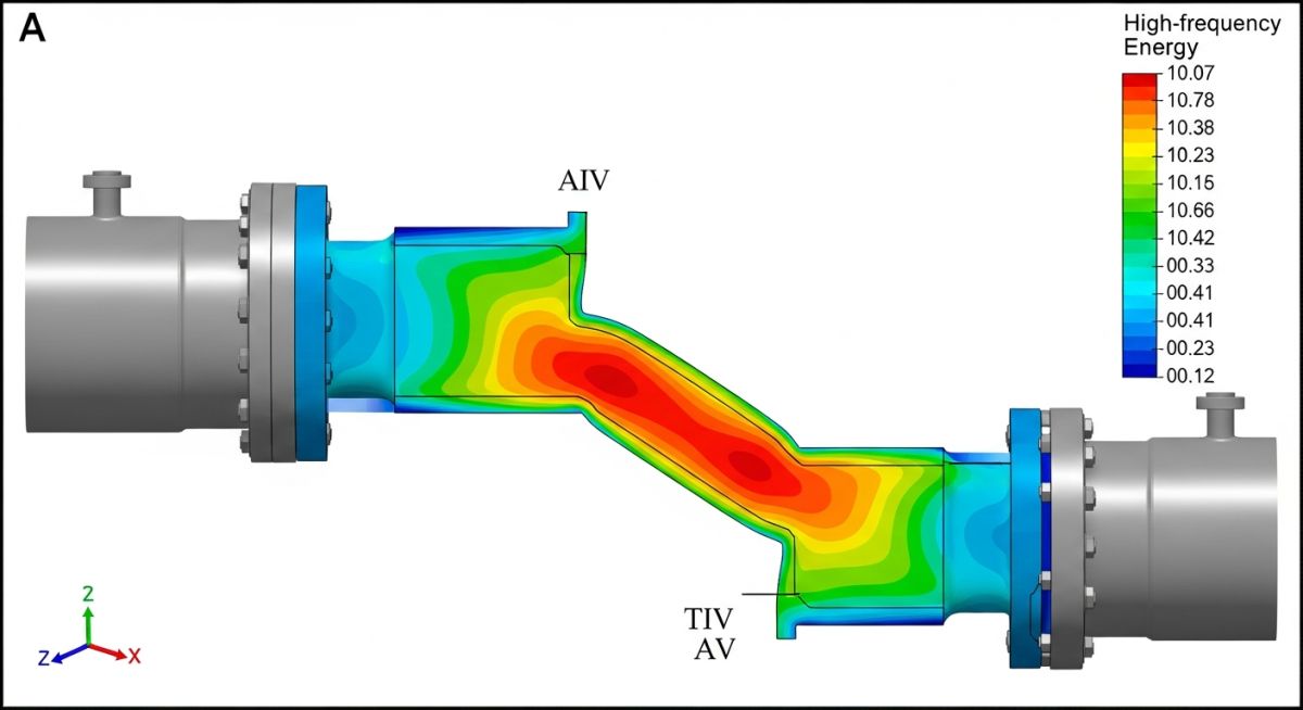
What is Acoustic-Induced Vibration or AIV?
In my two decades of piping integrity management, I have seen too many small-bore connections fail within weeks of commissioning due to overlooked acoustic energy. AIV is not merely “noise”; it is a mechanical force that manifests as high-frequency shell-mode vibration. When high-pressure gas drops across a control valve or orifice, the resulting acoustic power can exceed 150 decibels, creating a sonic environment that forces the pipe wall to vibrate at its natural frequency.
Unlike Flow-Induced Vibration (FIV), which typically affects low-frequency structural modes, AIV targets the shell-mode resonance of the pipe itself. If you are designing high-pressure gas systems, you must account for the acoustic power level (PWL) and the transmission loss through the pipe wall. Failure to mitigate this leads to rapid crack propagation at branch connections, welds, and small-bore attachments.
Key Takeaways for Piping Integrity
- AIV is driven by high-frequency acoustic energy from pressure-reducing valves (PRVs).
- Shell-mode resonance is the primary failure mechanism for small-bore piping.
- Mitigation requires calculating the Acoustic Power Level (PWL) per Energy Institute (EI) guidelines.
- Wall thickness increases and damping are primary defense strategies against fatigue.
Understanding Acoustic-Induced Vibration in Piping Systems
Acoustic-Induced Vibration (AIV) Mechanics: AIV is a phenomenon where high-frequency acoustic energy generated by turbulent flow in pressure-reducing devices couples with the structural shell modes of the piping system, leading to high-cycle fatigue failure.
When gas passes through a restriction, such as a control valve, the kinetic energy is converted into acoustic energy. This energy propagates downstream as sound waves. The intensity of this sound is measured as the Acoustic Power Level (PWL). According to the Energy Institute (EI) Guidelines, the critical threshold for AIV risk is often cited at a PWL of 150 decibels. Beyond this level, the acoustic energy is sufficient to excite the pipe wall into high-frequency vibration.
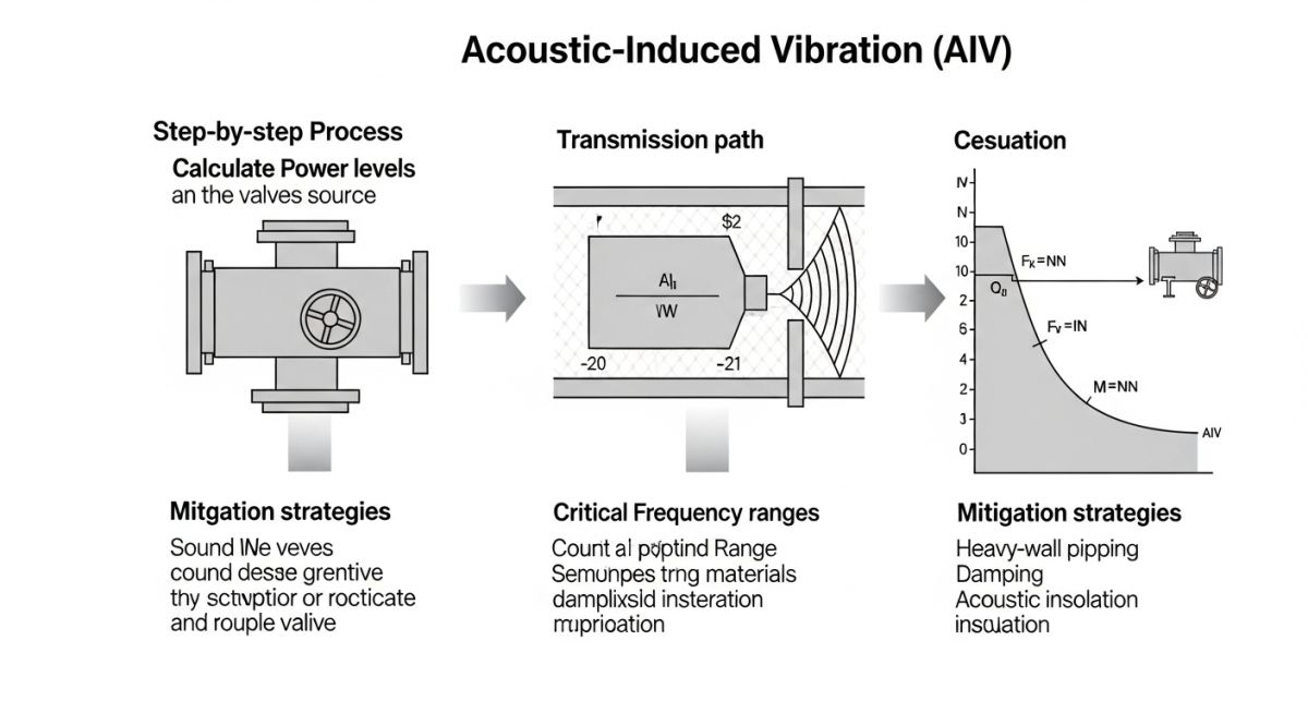
The calculation of PWL is fundamental to the design process. It is derived from the mass flow rate, the pressure drop across the valve, and the specific heat ratio of the gas. The formula for PWL is generally expressed as:
PWL = 10 * log10(Mechanical Power) + Efficiency Factor
In my experience, the most dangerous locations are downstream of the valve, specifically at branch connections, thermowells, and small-bore piping. These components act as stress concentrators. When the acoustic frequency matches the natural shell-mode frequency of the pipe, the resulting stress cycles can reach millions of cycles in a matter of days, leading to catastrophic fatigue failure.
Field Warning: The Small-Bore Trap
Never assume that standard piping supports are sufficient for AIV. Small-bore connections, such as pressure gauges or vent lines, are often overlooked during the initial stress analysis. These components have high natural frequencies that can easily align with the acoustic excitation frequencies, leading to rapid failure at the weld toe.
To mitigate these risks, engineers must perform a rigorous screening process. This involves calculating the PWL and comparing it against the allowable limits defined in ASME B31.3 and related industry best practices. If the PWL exceeds the threshold, design modifications are mandatory. These include increasing the pipe wall thickness to increase stiffness, installing acoustic insulation, or using heavy-walled fittings at branch connections.
Furthermore, the use of acoustic silencers or diffusers upstream of the valve can significantly reduce the source energy. In my practice, I prioritize the reduction of the source energy before relying on structural reinforcement. This approach ensures that the entire downstream system is protected, rather than just reinforcing individual components that might still be susceptible to fatigue.
AIV Mitigation Strategies: Implementing proactive AIV mitigation involves balancing structural reinforcement costs against the long-term operational reliability of high-pressure gas piping systems.
Advantages of Proactive Mitigation
- Prevents catastrophic fatigue failure of small-bore connections.
- Reduces unplanned maintenance and emergency shutdown costs.
- Extends the fatigue life of downstream pressure-reducing valves.
- Ensures compliance with international safety and environmental standards.
- Minimizes risk of hazardous gas leaks in high-pressure facilities.
Disadvantages of Mitigation Measures
- Increased capital expenditure due to thicker pipe schedules.
- Higher installation complexity for acoustic insulation systems.
- Potential for increased weight requiring additional structural supports.
- Limited effectiveness if source energy is not properly characterized.
- Requires specialized engineering expertise for accurate modeling.
AIV Engineering Applications: Acoustic-Induced Vibration analysis is critical across various high-energy industrial sectors where gas compression and pressure reduction are central to the process flow.
Natural Gas Compression Stations
In gas transmission, large-scale pressure reduction stations are prone to AIV due to high mass flow rates. Engineers must evaluate the acoustic power generated by control valves to prevent fatigue in downstream piping headers and small-bore instrumentation lines.
Petrochemical Feedstock Processing
High-pressure hydrogen or ethylene lines often utilize complex valve manifolds that generate significant acoustic energy. AIV analysis here focuses on the integrity of branch connections and the potential for shell-mode resonance in thin-walled piping sections.
Power Generation Steam Systems
Steam let-down stations in power plants operate under extreme pressure differentials, creating intense acoustic environments. Mitigation often involves heavy-walled piping and specialized acoustic dampening materials to protect the integrity of the steam distribution network.
When evaluating piping systems for Acoustic-Induced Vibration (AIV), engineers must rely on standardized screening criteria to determine if the sound power level (PWL) exceeds the threshold for fatigue-inducing energy. The following table outlines the critical variables used in the Energy Institute (EI) guidelines and ASME-related best practices to assess the risk of high-frequency fatigue in small-bore connections and branch piping.
These parameters are essential for calculating the acoustic power generated by pressure reduction valves or high-velocity gas flow. By comparing the calculated PWL against the allowable limits, we can identify which piping segments require reinforcement, such as gussets or heavy-wall fittings, before the system is commissioned. Always verify that your specific fluid properties, including the ratio of specific heats and molecular weight, are updated to reflect actual operating conditions rather than design-case assumptions.
| Parameter | Symbol | Standard Reference | Application |
|---|---|---|---|
| Sound Power Level | PWL | EI Guidelines | AIV Screening |
| Mass Flow Rate | m | ASME B31.3 | Energy Calculation |
| Pressure Drop | dP | API 521 | Source Intensity |
The following matrix maps the core entities involved in AIV analysis to their respective technical domains and governing standards. Understanding these relationships is vital for piping engineers who must bridge the gap between process simulation data and mechanical integrity requirements. Each entity represents a specific physical phenomenon or structural constraint that dictates the fatigue life of the piping system.
By maintaining this mapping, you ensure that your design documentation remains compliant with industry expectations for high-frequency vibration mitigation. Note that while ASME B31.3 provides the framework for pressure integrity, the specific fatigue limits for AIV are often derived from empirical data found in the Energy Institute guidelines, which should be treated as the primary reference for acoustic energy management in high-pressure gas systems.
| Entity | Domain | Standard |
|---|---|---|
| Small Bore Connection | Structural | ASME B31.3 |
| Acoustic Power | Fluid Dynamics | EI Guidelines |
| Fatigue Limit | Metallurgy | ASME BPVC VIII |
AIV Mitigation Compliance: Ensuring that your piping system is protected against acoustic-induced vibration requires a systematic approach to both design review and field verification. This checklist serves as a baseline for engineers to audit existing installations or validate new construction against the risk of high-frequency fatigue failure.
- ☐ Source Identification: Confirm all pressure reduction valves and high-velocity orifices are identified in the P&ID.
- ☐ PWL Calculation: Verify that the sound power level (PWL) has been calculated for all potential noise sources.
- ☐ Small-Bore Audit: Inspect all branch connections, vents, and drains for adequate gusseting or reinforcement.
- ☐ Support Integrity: Ensure that all piping supports are tight and that no loose components are present near high-noise zones.
- ☐ Material Verification: Confirm that the wall thickness of branch connections meets the requirements for high-frequency fatigue resistance.
- ☐ Operational Baseline: Document the vibration levels during initial startup to establish a baseline for future condition monitoring.
When performing these checks, prioritize the areas immediately downstream of pressure reduction valves, as these are the most common locations for AIV-related failures. If you identify a high-risk connection, document the specific geometry and consult the ASME B31.3 code for guidance on reinforcement requirements. Always remember that AIV is a high-frequency phenomenon; therefore, standard low-frequency vibration monitoring equipment may not capture the full extent of the energy present in the pipe wall. Use specialized high-frequency accelerometers if you suspect that the vibration levels are approaching the fatigue threshold of the material.
Problem: High-Frequency Fatigue in Gas Processing Plant
A major gas processing facility experienced repeated failures of 2-inch branch connections located downstream of a high-pressure letdown valve.
- Excessive noise levels exceeding 110 dBA near the valve outlet.
- Lack of gusseting on small-bore connections, leading to stress concentration.
- High-velocity gas flow creating intense acoustic energy.
- Fatigue cracks propagating from the weld toe of the branch connection.
Outcome: Successful Mitigation and System Stabilization
The engineering team implemented a comprehensive remediation strategy that significantly reduced the risk of future fatigue failures.
- Installed heavy-duty gussets on all small-bore connections within the high-noise zone.
- Replaced standard fittings with thicker-walled components to increase structural stiffness.
- Applied acoustic insulation to the piping to dampen the transmission of sound waves.
- Established a recurring inspection program using ultrasonic testing to monitor weld integrity.
In my experience, the key to solving this issue was not just the physical reinforcement, but the rigorous application of the Energy Institute guidelines to quantify the acoustic energy. By treating the piping system as a dynamic structure rather than just a pressure vessel, we were able to predict the failure points before they occurred. I recommend that all engineers working on high-pressure gas systems perform an AIV screening during the FEED stage to avoid these costly field modifications.
How does AIV differ from Flow-Induced Vibration?
- AIV is driven by high-frequency acoustic energy generated by pressure drops, typically affecting small-bore connections.
- FIV is caused by direct fluid impingement or vortex shedding, which usually impacts larger piping components or unsupported spans.
- AIV is characterized by high-frequency noise, whereas FIV often manifests as lower-frequency, large-amplitude movement.
- Mitigation for AIV focuses on structural stiffness and acoustic damping, while FIV mitigation often involves changing the piping geometry or adding structural supports to shift natural frequencies.
What are the primary ASME standards for AIV?
- Engineers typically supplement ASME B31.3 with the Energy Institute (EI) guidelines for AIV assessment.
- ASME BPVC Section VIII is used to evaluate the fatigue life of pressure-containing components under cyclic loading.
- API 521 provides guidance on pressure relief systems, which are common sources of acoustic energy.
- Compliance is achieved by ensuring that the calculated stress ranges from AIV do not exceed the allowable fatigue limits defined in the relevant ASME codes.
Why do small-bore connections fail most often?
- They often have a high natural frequency that can coincide with the high-frequency acoustic energy generated by valves.
- The weld connection at the main header acts as a stress concentration point, making it prone to fatigue crack initiation.
- These connections are frequently unsupported, allowing for significant vibration amplitude during acoustic excitation.
- The mass of the attached instrumentation or valve can further amplify the vibration, leading to rapid fatigue failure.
How can I calculate the sound power level?
- The calculation requires input data such as mass flow rate, pressure drop, and fluid properties like the ratio of specific heats.
- Standard formulas provided in the Energy Institute guidelines are used to estimate the acoustic energy generated by the valve.
- The result is expressed in decibels (dB) and is compared against the threshold limits for the specific piping diameter and wall thickness.
- If the calculated PWL exceeds the limit, the piping segment is flagged for further analysis or structural reinforcement.
What is the role of gussets in AIV?
- They increase the stiffness of the branch connection, shifting its natural frequency away from the excitation frequency.
- Gussets reduce the stress concentration at the weld toe, which is the most common site for fatigue crack initiation.
- By providing additional support, they limit the displacement of the branch connection during high-frequency vibration.
- Properly designed gussets are essential for ensuring the long-term integrity of small-bore connections in high-noise environments.
Can acoustic insulation help with AIV?
- It helps to dampen the transmission of sound waves through the pipe wall, reducing the overall noise level.
- While it does not eliminate the source of the vibration, it can reduce the energy transferred to the surrounding structure.
- Insulation is often used in conjunction with structural reinforcement to provide a comprehensive mitigation strategy.
- It is important to ensure that the insulation material is compatible with the operating temperature and environment of the piping system.
📚 Recommended Resources: Acoustic-Induced Vibration
Complete Course on
Piping Engineering
Check Now
Key Features
- 125+ Hours Content
- 500+ Recorded Lectures
- 20+ Years Exp.
- Lifetime Access
Coverage
- Codes & Standards
- Layouts & Design
- Material Eng.
- Stress Analysis
