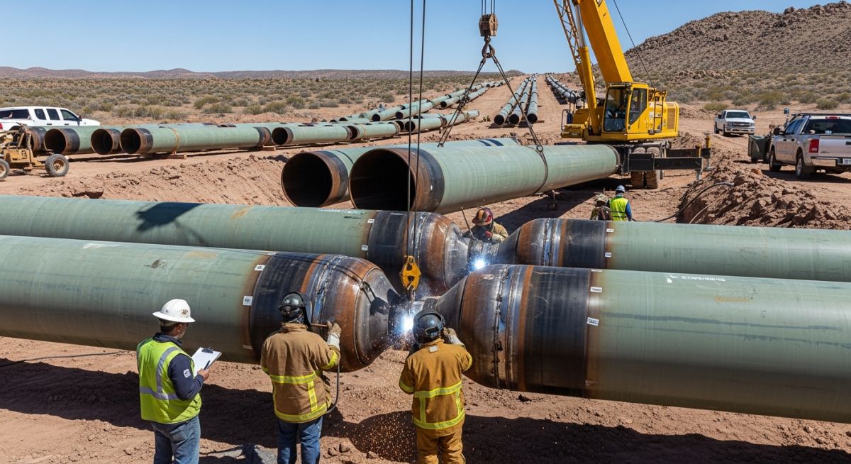
Pipelines Material Selection: Engineering Standards and Best Practices
In my two decades of field experience, I have seen that the most common cause of premature pipeline failure is not poor welding, but improper material selection during the FEED stage. Selecting the right steel grade or alloy is a balancing act between mechanical strength, weldability, and resistance to the specific chemical cocktail flowing through the line.
Whether you are dealing with sour service environments or high-pressure cryogenic transport, your material choice dictates the entire lifecycle cost and safety profile of the asset. This guide breaks down the technical rigor required to navigate material specifications effectively.
Key Takeaways
- Master the application of API 5L grades for carbon steel line pipe.
- Understand the impact of H2S and CO2 on material degradation.
- Align material selection with ASME B31.3 pressure-temperature ratings.
- Implement rigorous testing protocols for high-alloy and exotic materials.
Technical Deep-Dive: Pipelines Material Selection Protocols
Pipelines Material Selection: A rigorous engineering discipline requiring the evaluation of mechanical properties, fracture toughness, and corrosion resistance against the specific operating envelope defined by international codes.
When I evaluate a project, I start with the fluid composition. If the process fluid contains hydrogen sulfide, we must immediately pivot to NACE MR0175/ISO 15156 compliance. The material must resist Sulfide Stress Cracking (SSC) and Hydrogen Induced Cracking (HIC). For standard carbon steel, API 5L X52 or X60 are common, but their chemical composition—specifically the sulfur and phosphorus content—must be strictly controlled to ensure weldability and toughness.
Stress Parameters and Design Limits
The design pressure and temperature dictate the wall thickness calculation per ASME B31.3. The formula for pressure design of straight pipe is based on the allowable stress (S), which is temperature-dependent. As the temperature rises, the allowable stress decreases, requiring a thicker wall to maintain the same pressure rating.
Field Warning: Material Ductility
Never overlook the Ductile-to-Brittle Transition Temperature (DBTT). In cold climates, selecting a material with insufficient Charpy V-Notch impact energy can lead to catastrophic brittle fracture. Always verify the minimum design metal temperature (MDMT) against the material’s impact test requirements.
For high-pressure gas transmission, we often utilize API 5L PSL2 pipe. The “PSL2” designation implies mandatory toughness testing and stricter chemical limits compared to PSL1. This is non-negotiable for high-consequence areas where a rupture could lead to significant environmental or safety impacts.
When calculating the required thickness (t), we use the formula: t = (P * D) / (2 * (S * E + P * Y)), where P is internal design pressure, D is outside diameter, S is allowable stress, E is the quality factor, and Y is the coefficient for temperature. In my experience, the selection of the Y coefficient is often where junior engineers make errors; it must be selected based on the material type and temperature range specified in the code tables.
Material Selection Trade-offs: The strategic evaluation of material performance versus economic feasibility, balancing long-term asset integrity against initial capital expenditure.
Advantages
- Standardized API 5L grades ensure global supply chain availability.
- High-strength steels (X70/X80) allow for thinner walls, reducing total steel tonnage.
- Advanced corrosion-resistant alloys (CRAs) provide decades of service in harsh sour environments.
- Predictable mechanical behavior under standard operating conditions.
Disadvantages
- High-strength steels require specialized welding procedures to prevent hydrogen cracking.
- Exotic alloys (Inconel/Duplex) significantly increase initial project capital expenditure.
- Complex material specifications often lead to long lead times for procurement.
- Incompatibility between different material grades can cause galvanic corrosion at joints.
Industrial Pipeline Deployment: The application of specific material grades to meet the unique pressure, temperature, and chemical demands of diverse energy infrastructure sectors.
High-Pressure Natural Gas Transmission
Utilizing API 5L X70 PSL2 steel is standard for long-distance gas transmission lines to optimize wall thickness while maintaining high fracture toughness. This material choice is critical for managing the high hoop stresses encountered in large-diameter pipelines operating at pressures exceeding 100 bar.
Sour Service Oil Gathering Systems
In fields with high H2S concentrations, we specify carbon steel with controlled sulfur content and specific heat treatment to meet NACE MR0175 requirements. This prevents the initiation of sulfide stress cracking, which is the primary failure mechanism in untreated carbon steel gathering lines.
Cryogenic Liquefied Natural Gas (LNG) Piping
For LNG service, we move away from standard carbon steel to austenitic stainless steels like 304L or 316L, which maintain excellent ductility at temperatures as low as -162 degrees Celsius. These materials are essential to prevent brittle failure in the extreme cold of the liquefaction and storage process.
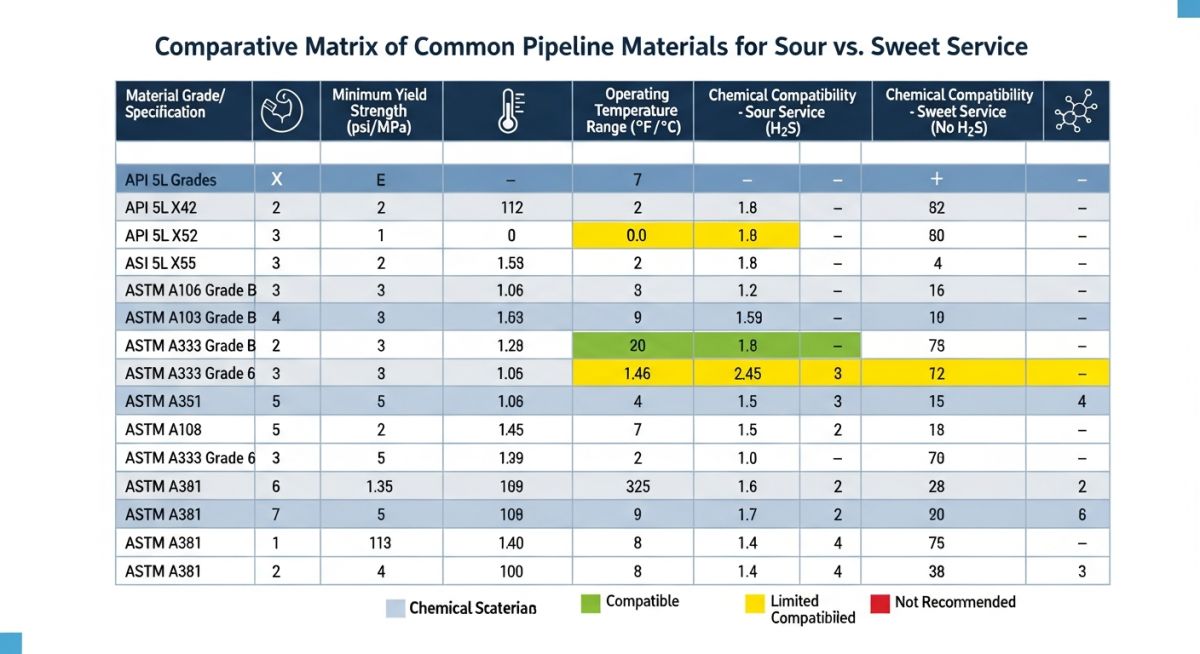
Selecting the correct material grade is the cornerstone of pipeline integrity, particularly when navigating the complex requirements of ASME B31.3 and API 5L. The following table provides a comparative analysis of common carbon steel grades used in high-pressure oil and gas transmission, focusing on yield strength, toughness, and typical service limitations. Engineers must evaluate these parameters against the specific design pressure and temperature profiles of their project to avoid premature fatigue or brittle fracture.
When reviewing these specifications, note that the transition from Grade B to X-series steels involves significant changes in micro-alloying elements, which directly influence weldability and hydrogen-induced cracking (HIC) resistance. Always verify the mill test reports against the project-specific supplementary requirements to ensure that the material chemistry aligns with the intended welding procedure specifications (WPS) and heat treatment protocols.
| Material Grade | Min Yield (MPa) | Typical Application | Standard Reference |
|---|---|---|---|
| API 5L Grade B | 245 | General Utility/Low Pressure | API 5L |
| API 5L X52 | 360 | Transmission Pipelines | API 5L |
| API 5L X65 | 450 | High-Pressure Sour Service | API 5L |
| ASTM A106 Gr B | 240 | Process Piping/Refinery | ASME B31.3 |
The following matrix maps critical engineering entities to their respective regulatory frameworks and physical performance indicators. This mapping is essential for cross-referencing material properties during the procurement and quality assurance phases of a project. By aligning these entities, we ensure that the design basis remains consistent from the initial FEED stage through to final commissioning and operational maintenance.
Each entity listed represents a specific technical domain that influences the overall structural integrity of the pipeline system. Understanding the interplay between these variables—such as the relationship between carbon equivalent (CE) and weldability—is vital for preventing catastrophic failures in the field. Use this matrix as a quick-reference guide during design reviews to confirm that all selected materials meet the necessary code-mandated safety factors.
| Entity | Primary Parameter | Standard |
|---|---|---|
| Carbon Equivalent | Weldability Index | API 5L |
| Charpy V-Notch | Fracture Toughness | ASME B31.3 |
| Hardness (HRC) | Sour Service Limit | NACE MR0175 |
Ensuring that the specified materials are correctly installed and verified in the field is a critical step in the quality control process. My experience has shown that even the most robust design can fail if the material procurement or installation deviates from the approved specifications. This checklist serves as a final gatekeeper for site engineers and inspectors to validate that all components meet the stringent requirements of ASME B31.3 and API 5L.
- Material Traceability: Verify that all pipe joints and fittings have clear heat numbers and manufacturer markings that match the Material Test Reports (MTRs).
- Visual Inspection: Check for surface defects, laminations, or mechanical damage that could compromise the structural integrity of the pipe wall.
- Wall Thickness Verification: Use ultrasonic thickness gauges to confirm that the delivered pipe wall thickness meets the nominal requirements specified in the design drawings.
- Hardness Testing: For sour service applications, perform field hardness testing to ensure the material remains below the maximum allowable limits defined by NACE MR0175.
- Weld Procedure Compliance: Confirm that the welding consumables used on-site are compatible with the base material grade and that the WPS is qualified for the specific wall thickness.
Always document these verification steps in the project quality record book. If any discrepancy is found, immediately quarantine the material and initiate a non-conformance report (NCR) to prevent the installation of substandard components that could lead to future operational hazards.
The Problem: Premature Cracking in Sour Service Pipeline
A high-pressure gas transmission line experienced localized cracking near the heat-affected zone (HAZ) of field welds after only six months of operation.
- Material hardness exceeded the NACE limit of 22 HRC due to improper cooling rates.
- The welding procedure did not account for the high carbon equivalent of the selected X65 grade.
- Lack of post-weld heat treatment (PWHT) in a high-stress environment.
- Inadequate pre-heat temperatures during the winter installation phase.
The Outcome: Successful Remediation and Integrity Restoration
The project team successfully restored the pipeline integrity by implementing a revised welding and inspection protocol.
- Re-qualified the welding procedure with strict control over interpass temperatures.
- Implemented 100% hardness testing on all field welds to ensure compliance with NACE standards.
- Replaced affected pipe segments with material having a lower carbon equivalent.
- Established a continuous monitoring program using ultrasonic sensors to detect early-stage crack growth.
My recommendation for similar projects is to prioritize material chemistry verification during the procurement phase. Never assume that the mill-supplied material is automatically suitable for sour service without performing independent verification tests, especially when the project involves complex field welding conditions.
How does carbon equivalent influence weldability?
- High CE steels require strict pre-heat and post-heat controls to prevent hydrogen-induced cracking.
- Engineers must calculate the CE using the International Institute of Welding (IIW) formula.
- Lowering the CE is often necessary for high-strength grades to maintain ductility in the weld zone.
What are the primary requirements for sour service?
- Materials must be limited to a maximum hardness of 22 HRC to prevent brittle failure.
- Microstructure control is essential to avoid elongated manganese sulfide inclusions.
- Strict control over chemical composition, particularly sulfur and phosphorus levels, is required.
When is Charpy V-Notch testing required?
- Testing is mandatory for materials operating below the ductile-to-brittle transition temperature.
- ASME B31.3 provides specific exemption curves based on material thickness and temperature.
- Impact energy requirements are defined by the code to ensure the material can absorb energy without catastrophic failure.
How do I select between API 5L and ASTM A106?
- API 5L offers a wider range of high-strength grades (X-series) for long-distance transmission.
- ASTM A106 is preferred for plant piping where high-temperature pressure containment is the primary concern.
- Always verify the specific code requirements for the project, as they may mandate one standard over the other.
What is the role of mill test reports?
- MTRs must be reviewed by a qualified engineer to ensure all parameters are within the specified limits.
- They serve as the basis for material traceability throughout the project lifecycle.
- Discrepancies in MTRs must be addressed before the material is released for fabrication or installation.
How does wall thickness affect design safety?
- ASME B31.3 provides the formulas for calculating the minimum required wall thickness.
- Increasing wall thickness improves pressure resistance but also increases the weight and cost of the pipeline.
- Engineers must balance structural requirements with economic considerations and constructability constraints.
📚 Recommended Resources: Pipelines Material Selection
Read these Guides
- 📄 Mastering Hydrogen Compression Systems: Engineering Design, Selection, and Safety
- 📄 Piping Materials vs Pipeline Materials: Key Differences and Engineering Standards
- 📄 Piping Insulation: Functions, Materials, and Types of Pipe Insulation
- 📄 Surge Relief Valve Design Function Types and Selection Guide
🎓 Advanced Training


Complete Course on
Piping Engineering
Check Now
Key Features
- 125+ Hours Content
- 500+ Recorded Lectures
- 20+ Years Exp.
- Lifetime Access
Coverage
- Codes & Standards
- Layouts & Design
- Material Eng.
- Stress Analysis
