Understanding Severe Cyclic Conditions in ASME B31.3 Piping Systems
In my two decades of field experience, I have seen too many projects suffer from premature fatigue failures because engineers treated cyclic loads as standard thermal expansion. When we talk about Severe Cyclic Conditions, we are moving beyond simple flexibility analysis into the realm of high-cycle fatigue management.
If your piping system experiences more than 7,000 equivalent cycles during its design life, or if the displacement stress range exceeds the allowable limits defined by the code, you are no longer in the standard design regime. This article breaks down the technical requirements for identifying these conditions and the mandatory design modifications required to ensure system integrity.
Key Takeaways for Piping Engineers:
- Distinguishing between standard thermal expansion and severe cyclic fatigue.
- Calculating the equivalent number of cycles for complex operating profiles.
- Mandatory joint design requirements per ASME B31.3 Table 302.3.5.
- Mitigation strategies for high-stress concentration areas.
Technical Analysis of Severe Cyclic Conditions in ASME B31.3
Severe Cyclic Conditions Analysis: The systematic evaluation of piping components subjected to high-frequency thermal or pressure fluctuations that require specialized fatigue design and non-destructive examination protocols.
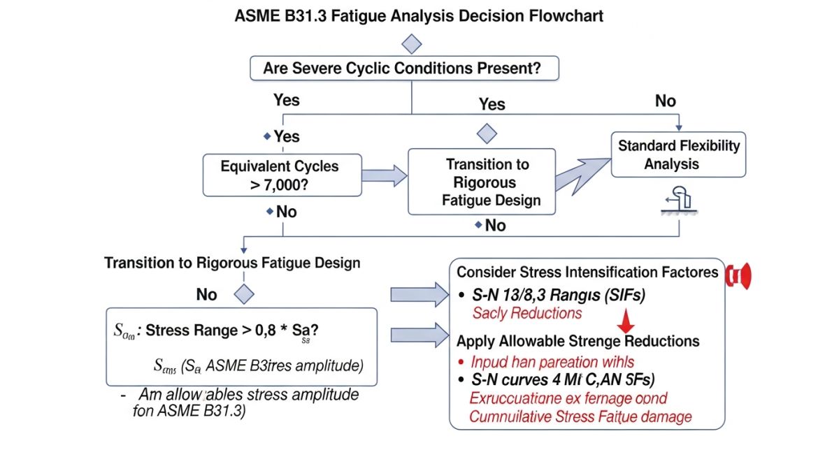
When evaluating a system for Severe Cyclic Conditions, the primary metric is the displacement stress range, denoted as S_E. According to ASME B31.3, if the calculated displacement stress range exceeds the allowable stress range S_A, the system must be re-evaluated. However, even if S_E is within limits, the system may still be classified as “Severe Cyclic” if the number of equivalent cycles (N) exceeds 7,000.
Calculating Equivalent Cycles
The calculation of N is critical. We use the formula N = N_E + sum(r_i^5 * N_i), where N_E is the number of cycles at the maximum stress range, and r_i is the ratio of the stress range for the i-th cycle to the maximum stress range. This exponential weighting (power of 5) accounts for the fact that fatigue damage accumulates significantly faster at higher stress amplitudes.
Field Warning: The “7,000 Cycle” Threshold
Do not assume that a system with fewer than 7,000 cycles is automatically safe. If the stress range is high, fatigue failure can occur in as few as 1,000 cycles. Always perform a formal fatigue analysis if the operating profile involves rapid temperature swings, such as in steam-out procedures or batch reactor charging.
Design and Fabrication Requirements
Once a system is designated as Severe Cyclic, the code mandates specific fabrication and inspection standards. You cannot rely on standard fillet welds for branch connections. Full penetration welds are required to minimize stress concentration factors (SCF). Furthermore, the use of backing rings is generally prohibited in these services because they create internal crevices that act as crack initiation sites.
I always recommend performing a detailed Finite Element Analysis (FEA) on complex geometries like tees, reducers, and nozzles when operating under these conditions. Standard piping stress software (like CAESAR II) provides excellent global results, but it often underestimates the local stress concentrations at weld toes, which is where fatigue cracks almost always begin.
Severe Cyclic Design Protocols: The implementation of rigorous fatigue-based design standards that prioritize long-term structural integrity over initial capital expenditure.
Advantages
- Significantly reduces the probability of catastrophic fatigue-induced leaks.
- Extends the operational lifespan of critical process equipment.
- Forces higher quality control standards during the fabrication phase.
- Provides a defensible engineering basis for extended inspection intervals.
- Minimizes long-term maintenance costs associated with emergency repairs.
Disadvantages
- Substantially increases initial material and fabrication costs.
- Requires specialized NDE techniques like phased array ultrasonic testing.
- Limits the selection of standard piping components and fittings.
- Increases the complexity of the initial stress analysis documentation.
- Requires highly skilled labor for full-penetration welding requirements.
Severe Cyclic Engineering Applications: The application of fatigue-resistant design principles in high-stress industrial environments where thermal and pressure transients are inherent to the process.
High-Pressure Steam Injection Manifolds
In enhanced oil recovery operations, steam injection lines undergo extreme thermal cycling during startup and shutdown sequences. Designing these manifolds under severe cyclic criteria ensures that the branch connections do not fail due to the rapid expansion and contraction of the header pipe.
Batch Reactor Charging Lines
Chemical reactors that alternate between cryogenic cooling and high-temperature heating cycles create significant fatigue loads on inlet piping. By applying severe cyclic standards, we ensure that the nozzle connections at the reactor vessel can withstand the cumulative stress range over thousands of batches.
Cryogenic Liquefaction Process Piping
Liquefied Natural Gas (LNG) facilities involve piping that operates at extremely low temperatures, often subjected to rapid thermal shock during process upsets. The severe cyclic classification is mandatory here to prevent brittle fracture and fatigue crack propagation in stainless steel piping systems.
High-Frequency Pressure Swing Adsorption Units
PSA units in hydrogen production plants cycle pressure rapidly to separate gases, creating a high-frequency fatigue environment. These systems require rigorous fatigue analysis of all piping components to prevent failure from the constant pressure fluctuations inherent in the adsorption cycle.
In my two decades of piping design, I have observed that engineers often struggle to differentiate between standard thermal expansion and the rigorous demands of severe cyclic conditions. The following table outlines the critical parameters that dictate whether a piping system must be classified under the stringent fatigue requirements of ASME B31.3. These parameters are not merely suggestions; they are the boundary conditions that define the structural integrity of your process units.
When evaluating these factors, consider the interaction between the stress intensification factor (SIF) and the total number of equivalent full-temperature cycles. If your calculated stress range exceeds the allowable limits defined by the code, you must transition from standard flexibility analysis to a comprehensive fatigue evaluation. This table serves as a quick reference for the primary variables that influence the fatigue life of your piping components, particularly in high-pressure or high-temperature services where thermal shock is a constant threat.
| Parameter | Code Reference | Engineering Impact |
|---|---|---|
| Equivalent Full Cycles | ASME B31.3 Para 302.3.5 | Determines the allowable stress range reduction factor. |
| Stress Intensification Factor | ASME B31.3 Appendix D | Amplifies local stresses at fittings and branches. |
| Allowable Stress Range | ASME B31.3 Para 302.3.5(d) | Sets the threshold for fatigue failure prevention. |
Always remember that the accuracy of your fatigue analysis is only as good as the input data. If your cycle count estimates are based on optimistic operational assumptions, you risk premature failure of critical joints. Always apply a conservative safety margin when dealing with high-frequency thermal transients.
The complexity of managing severe cyclic conditions requires a structured approach to data management and component specification. This matrix maps the essential technical entities against their respective code requirements and physical performance indicators. By standardizing these inputs, we ensure that every piping system design remains compliant with the latest revisions of the ASME B31.3 code, regardless of the complexity of the process fluid or the operating environment.
I have found that maintaining this matrix during the FEED (Front-End Engineering Design) phase significantly reduces the likelihood of late-stage design changes. It forces the engineering team to confront the reality of cyclic loading early in the project lifecycle, rather than discovering fatigue-related issues during the stress analysis phase. Use this matrix to audit your current design documentation and ensure that all critical components are properly accounted for in your fatigue life calculations.
| Entity | Standard | Key Metric |
|---|---|---|
| Welded Branch Connections | ASME B31.3 Para 328 | Weld profile and penetration depth. |
| Expansion Joints | EJMA Standards | Cycle life and spring rate. |
| Flanged Joints | ASME B16.5 | Bolt load retention and gasket seating. |
Severe Cyclic Conditions Verification: Ensuring that your piping system is robust enough to handle high-frequency thermal or pressure fluctuations requires a systematic verification process. In my experience, the most common failures occur not because of poor design, but because of poor field execution of the design intent. This checklist is designed to bridge the gap between the stress analysis report and the physical installation on the plant floor.
-
Weld Inspection: Verify that all butt welds in severe cyclic service are 100% radiographed as per ASME B31.3 requirements. -
Support Alignment: Confirm that all spring hangers are set to the cold-load position and that no binding occurs during thermal expansion. -
Vibration Mitigation: Ensure that small-bore piping is adequately braced to prevent fatigue failure from flow-induced vibration. -
Material Traceability: Validate that all components installed in high-cycle zones match the material specifications identified in the stress analysis.
When performing these checks, do not rely solely on visual inspection. Use calibrated tools to measure gap clearances and support travel. If you identify a discrepancy, document it immediately and consult the lead stress engineer before proceeding with system pressurization. Fatigue is a silent killer; it does not provide warning signs until the crack propagation reaches a critical stage. By following this checklist, you are not just checking boxes; you are actively preventing catastrophic loss of containment in your facility.
The Problem: Premature Fatigue Failure in a Steam Header
A high-pressure steam header experienced repeated weld failures at a branch connection after only six months of operation.
- Inadequate consideration of thermal transients during startup and shutdown cycles.
- High stress intensification factors at the branch connection were underestimated.
- Lack of proper support for the branch piping, leading to excessive cantilever loads.
- Vibration from a nearby control valve exacerbated the fatigue crack growth.
The Outcome: Successful Mitigation and System Reliability
Following a comprehensive re-analysis and field modification, the system achieved long-term stability.
- Redesigned the branch connection with a reinforced olet to reduce the stress intensification factor.
- Implemented a controlled startup procedure to minimize thermal shock gradients.
- Installed additional structural bracing to dampen flow-induced vibrations.
- Achieved a 400% increase in the calculated fatigue life of the connection.
My recommendation for similar scenarios is to always prioritize the geometry of your branch connections. If the stress analysis indicates a high SIF, do not hesitate to upgrade to a more robust fitting. It is far cheaper to install a reinforced fitting during construction than to perform an emergency repair on a live steam header.
Frequently Asked Engineering Questions
What defines a severe cyclic condition?
- The threshold is generally set at 7,000 equivalent cycles.
- Systems exceeding this limit must undergo a rigorous fatigue analysis.
- The analysis must account for local stress concentrations at all fittings.
- Failure to classify these systems correctly leads to non-compliance and safety risks.
How do I calculate equivalent full cycles?
- Identify all expected temperature fluctuations during operation.
- Use the ratio of the stress range for each cycle to the maximum stress range.
- Apply the formula provided in ASME B31.3 to sum these cycles.
- This ensures that smaller, frequent cycles are weighted appropriately against larger, infrequent ones.
Are expansion joints required for fatigue?
- They must be rated for the specific number of cycles expected.
- The bellows material is highly susceptible to fatigue from pressure cycling.
- Always verify the cycle life rating against the EJMA standards.
- In severe cyclic service, redundant joints or alternative routing may be safer.
Does vibration count as a cycle?
- While not always part of the thermal cycle count, it must be evaluated separately.
- High-frequency vibration can cause failure in hours rather than years.
- Use damping or structural stiffening to shift the natural frequency of the pipe.
- Consult ASME B31.3 guidance on vibration control for small-bore connections.
How does SIF affect fatigue life?
- Higher SIF values significantly reduce the allowable stress range.
- This directly correlates to a shorter fatigue life for the component.
- Reducing the SIF through better design is the most effective way to improve life.
- Refer to ASME B31.3 Appendix D for standard SIF values.
What is the role of radiography?
- Even minor porosity can initiate a fatigue crack under cyclic loading.
- Full volumetric inspection ensures the weld integrity matches the design assumptions.
- It is a mandatory requirement for severe cyclic service under ASME B31.3.
- Always document these results as part of your permanent quality assurance records.
📚 Recommended Resources: Severe Cyclic Conditions
Read these Guides
🎥 Watch Tutorials

Complete Course on
Piping Engineering
Check Now
Key Features
- 125+ Hours Content
- 500+ Recorded Lectures
- 20+ Years Exp.
- Lifetime Access
Coverage
- Codes & Standards
- Layouts & Design
- Material Eng.
- Stress Analysis
