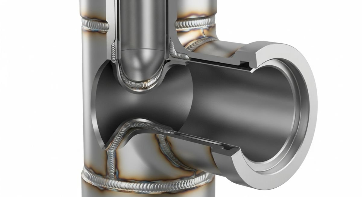
Tee Connections in Piping: Design and Dimensioning Standards
In my two decades of field experience, I have observed that the humble tee fitting is often the most misunderstood component during the initial piping layout phase. Whether you are dealing with high-pressure steam lines or corrosive chemical transport, selecting the correct tee—be it an equal tee or a reducing tee—is fundamental to maintaining system integrity and flow efficiency.
This guide dissects the technical nuances of tee connections, focusing on how to interpret dimensional tables, calculate branch reinforcement requirements, and ensure your piping design complies with international standards. We will move beyond basic definitions to explore the real-world implications of fitting geometry on fluid turbulence and structural stress.
Key Takeaways for Piping Designers
- Master the distinction between equal and reducing tee geometry.
- Understand the critical role of ASME B16.9 in ensuring dimensional consistency.
- Learn to identify when branch reinforcement is required per ASME B31.3.
- Optimize your piping layout to minimize pressure drop at branch junctions.
Technical Analysis of Tee Connections in Piping
Tee Connections in Piping: These components serve as the primary junction points for flow distribution, requiring precise alignment with pipe wall thickness and material specifications to prevent localized stress concentrations.
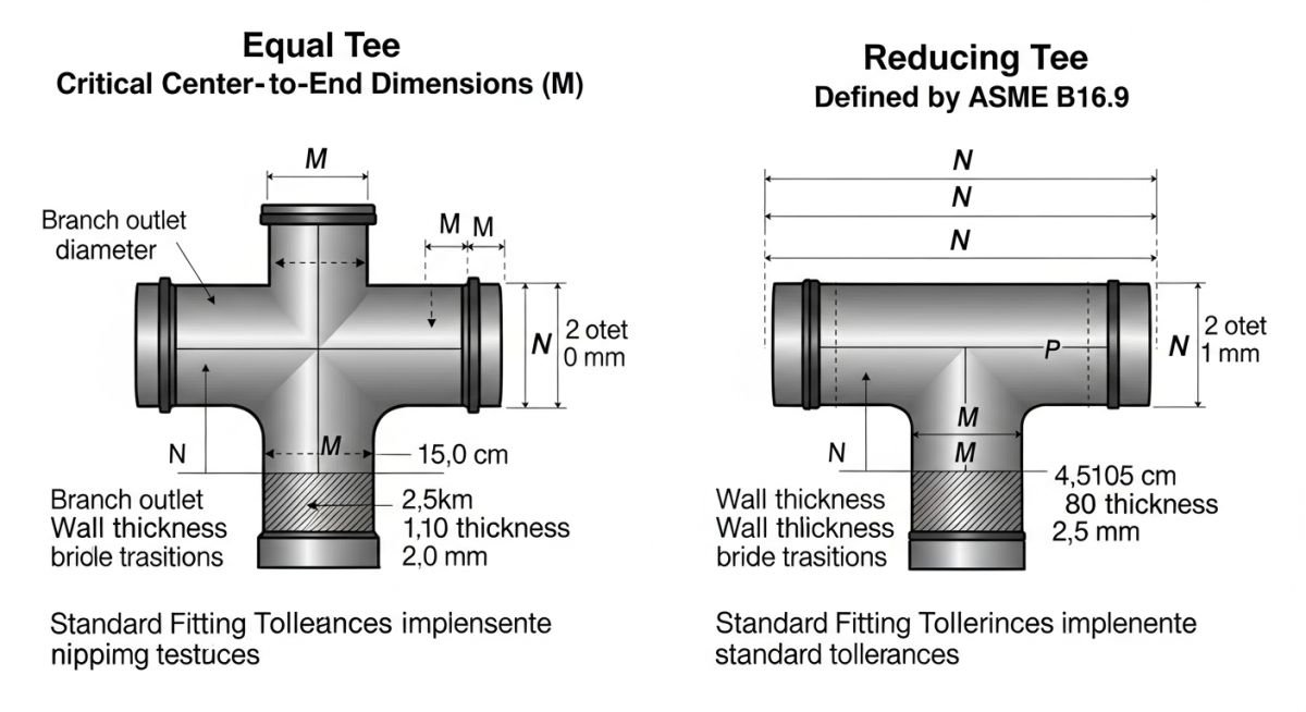
When designing a piping system, the selection of a tee is dictated by the branch-to-header size ratio. An equal tee is utilized when the branch pipe diameter matches the header pipe diameter, whereas a reducing tee is employed to transition flow into a smaller diameter branch line. According to ASME B16.9, these fittings must maintain a center-to-end dimension that ensures sufficient weld clearance for field installation.
Dimensional Parameters and Calculations
The primary dimensional constraint for a tee is the center-to-end (C) dimension. For a standard NPS 6 equal tee, the C dimension is fixed by the standard to ensure interchangeability. However, when calculating the pressure integrity of the junction, we must consider the stress intensification factor (SIF). The SIF for a tee is typically higher than that of a straight pipe, often calculated as 0.9 divided by the h-factor, where h is the characteristic of the fitting geometry.
Field Warning: Branch Reinforcement
Never assume a standard tee is sufficient for high-pressure or high-vibration services without verifying the branch reinforcement requirements per ASME B31.3. If the branch size is significant relative to the header, the intersection area may require additional weld metal or a reinforcing pad to compensate for the material removed during the branch opening.
In my experience, designers often overlook the impact of the “run” versus “branch” wall thickness. While the fitting body is designed to match the nominal pipe size (NPS) and schedule, the transition zone in a reducing tee creates a complex stress field. We calculate the required thickness ™ using the formula: tm = (P * D) / (2 * (S * E + P * Y)), where P is internal pressure, D is outside diameter, S is allowable stress, E is quality factor, and Y is a temperature-dependent coefficient.
Always ensure that the fitting schedule matches the connecting pipe schedule. A mismatch in wall thickness leads to a “step” at the weld joint, which acts as a stress riser and a site for potential fatigue cracking in cyclic service. When specifying these components, always reference the specific material grade, such as ASTM A234 WPB for carbon steel, to ensure compatibility with the piping specification.
Tee Connection Performance: Evaluating the structural and operational trade-offs of using factory-made tees versus alternative branch connection methods in industrial piping.
Advantages
- Superior structural integrity compared to field-fabricated branch connections.
- Standardized dimensions ensure rapid procurement and site installation.
- Optimized internal geometry reduces flow turbulence and pressure drop.
- Full compliance with ASME B16.9 simplifies the QA/QC inspection process.
- Consistent wall thickness transitions minimize weld-related stress risers.
Disadvantages
- Higher procurement costs compared to simple weldolets or branch-olets.
- Requires significant space for installation, limiting tight-radius piping layouts.
- Increased weight on support structures due to the mass of the fitting.
- Limited availability for exotic alloys or non-standard pipe schedules.
- Requires precise alignment during fit-up to avoid excessive root gap issues.
Industrial Piping Integration: Deploying standardized tee connections across diverse sectors to ensure fluid control and structural reliability in complex process environments.
High-Pressure Steam Distribution
In power generation facilities, equal tees are critical for distributing high-pressure steam to multiple turbine inlets. The use of ASME B16.9 fittings ensures that the junction can withstand extreme thermal expansion cycles without compromising the weld integrity at the branch connection.
Chemical Process Manifolds
Reducing tees are frequently utilized in chemical processing plants to transition from large-diameter main headers to smaller-diameter feed lines for reactors. This configuration allows for precise flow control while maintaining the structural rigidity required for handling corrosive or hazardous process fluids.
Oil and Gas Gathering Systems
In upstream gathering lines, tee connections facilitate the convergence of multiple wellhead streams into a single transport pipeline. The robust design of these fittings is essential for managing the pressure surges and potential slug flow conditions common in multi-phase hydrocarbon transport.
When designing piping systems, selecting the correct fitting dimensions is critical for maintaining structural integrity and flow efficiency. The following table outlines the center-to-end (C) dimensions for standard weight butt-welded tees as specified by ASME B16.9. These values are essential for spool fabrication and isometric drawing accuracy, ensuring that the pipe-to-fitting interface aligns perfectly with the piping class requirements.
Engineers must note that these dimensions represent the distance from the center of the run to the face of the branch or run end. Variations in wall thickness (Schedule 40, 80, 160) do not typically alter the center-to-end dimension for a given nominal pipe size, but they significantly impact the internal flow area and pressure rating. Always verify the specific material grade and pressure-temperature ratings against ASME B31.3 before finalizing your bill of materials.
| NPS (Inches) | Center to End (Run) | Center to End (Branch) |
|---|---|---|
| 1 | 38 mm | 38 mm |
| 2 | 64 mm | 64 mm |
| 4 | 105 mm | 105 mm |
| 8 | 178 mm | 178 mm |
The following matrix maps the critical technical entities involved in tee connection design. Understanding the relationship between these parameters is vital for piping engineers to ensure compliance with international standards and project-specific piping classes. Each entity serves a distinct purpose in the lifecycle of a piping system, from initial stress analysis to final site installation.
By cross-referencing these entities, you can quickly identify the governing standards for material selection, dimensional tolerances, and pressure containment. This matrix is designed to assist in the rapid verification of design data during the P&ID development and stress analysis phases, reducing the risk of procurement errors or field rework.
| Entity | Standard | Primary Function |
|---|---|---|
| Butt-Weld Tee | ASME B16.9 | Branching and flow distribution |
| Forged Tee | ASME B16.11 | High-pressure small-bore connections |
| Pressure Rating | ASME B31.3 | System safety and containment |
Field verification of tee connections is a non-negotiable step in quality assurance. Before welding or bolting, I always perform a systematic check to ensure that the installed components match the design intent and safety requirements. This checklist covers the essential verification points for both equal and reducing tees in high-pressure industrial environments.
- ☐Dimensional Accuracy: Verify the center-to-end dimensions against the isometric drawing to ensure proper fit-up without inducing external stress.
- ☐Material Traceability: Confirm that the heat number on the tee matches the Material Test Report (MTR) and the project piping class.
- ☐Weld Preparation: Inspect the bevel angle and root face of the tee ends to ensure they meet the requirements of the Welding Procedure Specification (WPS).
- ☐Orientation Check: Ensure the branch outlet is correctly oriented according to the P&ID, especially for reducing tees where flow directionality is critical.
- ☐Support Proximity: Check that no pipe supports are located too close to the tee, which could restrict thermal expansion or cause localized stress concentrations.
Following these steps prevents common field issues such as misalignment, stress-induced cracking, and premature failure. Always document your findings in the site inspection report, referencing the relevant ASME B16.9 tolerances to justify any minor deviations or to trigger a formal design review if the discrepancy exceeds allowable limits.
The Problem: Premature Fatigue Cracking
A high-pressure steam line experienced recurring leaks at a reducing tee connection, leading to significant downtime and safety concerns.
- Excessive vibration from nearby reciprocating pumps.
- Improperly specified tee wall thickness for the operating pressure.
- Lack of adequate pipe support near the branch connection.
- Thermal expansion stresses exceeding the design allowance.
The Outcome: Successful Remediation
By implementing a comprehensive redesign, we eliminated the failure points and restored system reliability.
- Replaced the tee with a heavy-wall forged fitting per ASME B16.11.
- Installed a secondary support structure to dampen vibration.
- Updated the piping stress model to account for thermal cycling.
- Achieved zero leaks over a 24-month operational period.
My recommendation for similar scenarios is to always prioritize stress analysis for branch connections. If the branch size is significant relative to the run, consider using reinforced tees or weldolets to distribute stress more effectively across the header pipe.
Frequently Asked Engineering Questions
What is the difference between an equal and reducing tee?
- Equal tees maintain consistent flow velocity across the junction.
- Reducing tees facilitate pressure drops or flow diversion to smaller equipment.
- Both must adhere to ASME B16.9 dimensional standards.
How do I determine the correct wall thickness for a tee?
- Consult ASME B31.3 for pressure-temperature ratings.
- Match the schedule of the tee to the schedule of the mating pipe.
- Account for corrosion allowance in your final thickness calculation.
Are there specific standards for forged tees?
- Forged fittings provide superior strength compared to cast alternatives.
- They are rated by pressure classes such as 3000, 6000, and 9000.
- Always verify the material compatibility with the process fluid.
What is the impact of thermal expansion on tee connections?
- Use expansion loops to absorb thermal movement.
- Ensure pipe supports allow for necessary thermal displacement.
- Perform stress analysis using software to validate the design.
How do I handle misalignment during tee installation?
- Use proper alignment clamps to hold the tee in place.
- Adjust the adjacent pipe spools to achieve a natural fit.
- If misalignment persists, stop work and request a field engineering review.
Can I use a tee for flow measurement?
- Ensure the branch connection is properly reinforced for the instrument weight.
- Follow standard piping practices for instrument tap locations.
- Avoid using tees as flow splitters if precise flow distribution is required.
📚 Recommended Resources: Tee Connections in Piping
Read these Guides
🎓 Advanced Training



Complete Course on
Piping Engineering
Check Now
Key Features
- 125+ Hours Content
- 500+ Recorded Lectures
- 20+ Years Exp.
- Lifetime Access
Coverage
- Codes & Standards
- Layouts & Design
- Material Eng.
- Stress Analysis
