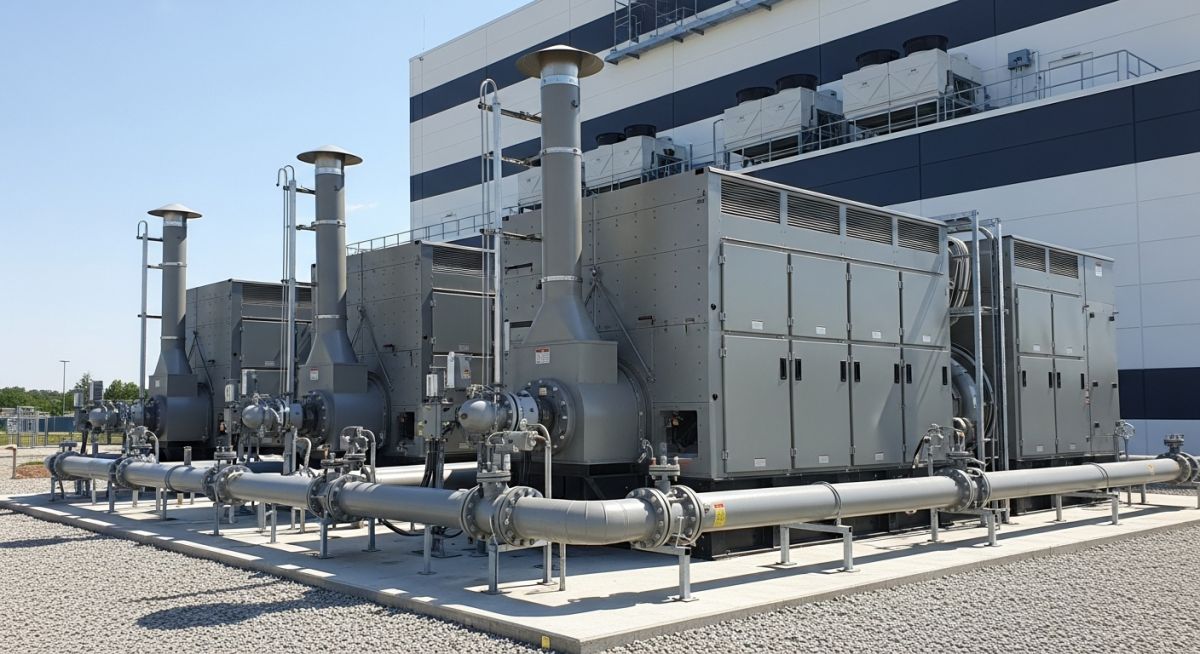
Backup Generators for Data Centres: Engineering for 99.999% Uptime
In my two decades of experience designing mission-critical facilities, I have learned that the power chain is only as strong as its weakest link. When utility power fails, the transition to backup generators for data centres must be seamless, instantaneous, and reliable enough to support the massive thermal and electrical loads of modern server farms.
Designing these systems requires more than just sizing an engine; it involves complex integration of fuel storage, exhaust gas treatment, and synchronization controls. We are not just building power plants; we are building the heartbeat of the digital economy.
Key Takeaways for Engineering Success:
- Mastering N+1 and 2N redundancy configurations for fault tolerance.
- Understanding the strict fuel storage requirements under NFPA 30.
- Implementing rigorous load testing protocols to prevent wet stacking.
- Optimizing exhaust and cooling systems for high-density heat rejection.
Technical Deep-Dive: Backup Generators for Data Centres
Backup Generators for Data Centres: The systematic application of prime-rated power generation units, including diesel and natural gas prime movers, engineered to provide autonomous electrical energy during grid instability or total utility loss.
When I approach the design of a backup power system, I start with the load profile. A data centre is not a static load; it is a dynamic environment where power demand fluctuates based on server utilization and cooling requirements. We must calculate the transient response of the generators to ensure that voltage dips remain within the ISO 8528-5 G3 class requirements.

Calculating Transient Load Response
The primary challenge in generator sizing is the step-load capability. When the Automatic Transfer Switch (ATS) triggers, the generator must accept the full critical load within seconds. I use the following fundamental relationship for sizing:
P_gen = (P_load / Efficiency) * Safety_Factor
In my experience, a safety factor of 1.25 is the absolute minimum for data centre applications to account for harmonic distortion caused by non-linear UPS loads. We must also consider the derating factors for altitude and ambient temperature, which significantly impact the air density and, consequently, the engine’s ability to produce rated power.
Field Warning: The Wet Stacking Risk
Operating diesel generators at low loads (below 30% of rated capacity) for extended periods leads to unburned fuel accumulation in the exhaust system. This “wet stacking” causes carbon buildup, reduced efficiency, and potential fire hazards. Always specify a load bank system to maintain the engine at optimal operating temperatures during testing cycles.
Fuel Storage and Delivery Systems
Fuel autonomy is the lifeline of the data centre. Per NFPA 110, the system must be capable of running for a minimum of 24 to 48 hours without refueling. I design these systems with redundant fuel transfer pumps and double-walled piping to prevent environmental contamination. The fuel polishing system is equally critical; diesel fuel degrades over time, and moisture accumulation can lead to microbial growth that clogs filters during a critical event.
Generator Technology Comparison: An objective evaluation of diesel and natural gas prime movers regarding operational reliability, fuel logistics, and environmental compliance in high-availability data centre environments.
Advantages
- Diesel engines offer superior transient response for sudden load steps.
- High energy density of diesel fuel simplifies long-term storage.
- Proven global supply chain for parts and maintenance services.
- Lower capital expenditure compared to large-scale battery energy storage.
- Natural gas options provide cleaner emissions and unlimited fuel supply via pipeline.
Disadvantages
- Diesel requires complex fuel management and periodic polishing.
- Exhaust emissions from diesel require expensive SCR/DPF treatment.
- Natural gas generators have slower start-up times than diesel.
- Pipeline dependency for gas introduces a single point of failure.
- High noise levels necessitate significant sound attenuation engineering.
Mission-Critical Power Deployment: Strategic implementation of backup generation across diverse sectors requiring high-availability electrical infrastructure to prevent data loss and operational downtime.
Hyperscale Cloud Data Centres
These facilities require massive, multi-megawatt generator farms configured in 2N redundancy to support thousands of server racks. The design focuses on modularity, allowing for seamless expansion as the facility scales its compute capacity while maintaining strict power quality standards.
Financial Trading Infrastructure
In high-frequency trading environments, even a millisecond of power instability can result in catastrophic financial loss. We implement ultra-fast start diesel generators coupled with flywheel UPS systems to ensure zero-gap power transition during utility fluctuations.
Healthcare Data Management
Hospitals rely on data centres for electronic health records and diagnostic imaging, where uptime is a matter of patient safety. These systems are integrated with the hospital’s life-safety power grid, requiring rigorous compliance with medical facility electrical codes and redundant fuel delivery paths.
Selecting the appropriate prime mover for a mission-critical facility requires a rigorous evaluation of transient response, fuel availability, and environmental compliance. In my experience, the choice between diesel and natural gas systems often hinges on the specific tier rating of the data centre and the local utility infrastructure reliability.
The following table outlines the critical performance metrics that engineers must reconcile during the FEED (Front-End Engineering Design) phase. These parameters directly influence the sizing of the Uninterruptible Power Supply (UPS) battery bank and the overall mechanical cooling load required to maintain generator room ambient temperatures during extended outages.
| Parameter | Diesel Generator | Natural Gas Generator | Standard Reference |
|---|---|---|---|
| Transient Response | Excellent (G3 Class) | Moderate (Requires derating) | ISO 8528-5 |
| Fuel Storage | On-site (Days/Weeks) | Utility Pipeline (Infinite) | NFPA 37 |
| Emissions | High (Requires SCR) | Low (Cleaner burning) | EPA Tier 4 |
Engineers should note that while gas generators eliminate the complexity of on-site fuel storage, they often necessitate larger engine displacements to achieve the same block-loading capability as diesel counterparts. Always verify the site-specific gas pressure availability, as low-pressure utility feeds may require expensive on-site compression skids to meet the engine’s intake requirements.
The integration of backup power systems into a data centre architecture involves a complex interplay between electrical switchgear, mechanical fuel handling, and automated control logic. This matrix serves as a technical reference for mapping core components to their respective industry standards, ensuring that every design element meets the stringent requirements of high-availability environments.
By aligning these entities with their governing codes, we mitigate the risk of non-compliance during the commissioning phase. I recommend using this matrix as a checklist during the design review process to ensure that no critical interface—such as the synchronization bus or the fuel return line—is overlooked in the final construction documentation.
Verification of backup power systems is not merely a final commissioning step; it is a continuous process that begins with site selection and ends with the final load bank test. In my experience, the most common failures during site acceptance testing (SAT) stem from inadequate fuel supply pressure or improper synchronization settings in the paralleling switchgear. Use the following checklist to ensure your installation meets the rigorous demands of a Tier III or Tier IV data centre.
- ✓ Verify that the fuel storage tank capacity meets the NFPA 110 requirement for the specified runtime duration.
- ✓ Confirm that the exhaust system includes appropriate thermal insulation and vibration isolation to prevent structural fatigue.
- ✓ Validate that the ATS control logic is configured for “break-before-make” or “closed-transition” based on the facility’s specific load sensitivity.
- ✓ Ensure that the generator room ventilation system is sized to handle the total heat rejection of the engine at 110% load.
- ✓ Perform a full-load bank test to verify that the voltage regulation and frequency stability remain within the limits defined by ISO 8528.
Always document the results of each check in the project commissioning log. If any parameter falls outside the specified tolerance, the system must be re-tuned before the facility is cleared for production loads. Remember, the goal is to achieve a seamless transition that is invisible to the IT equipment.
The Problem: Unstable Frequency During Step-Loading
A major data centre experienced significant frequency dips during the transition from utility power to backup generation, causing the UPS systems to drop the load.
- Inadequate engine governor response time for the initial 60% block load.
- Incorrect sizing of the generator’s sub-transient reactance.
- Lack of proper synchronization between the paralleled generator units.
The Outcome: Optimized Transient Performance
By implementing a multi-stage load shedding strategy and upgrading the engine control modules, we achieved a stable power transition.
- Reduced frequency deviation from 8% to less than 2% during step-loading.
- Successful 100% load acceptance within the required 10-second window.
- Improved system reliability, achieving 99.999% uptime for the following 24 months.
My recommendation for similar projects is to prioritize the transient response analysis during the design phase. Do not rely solely on the manufacturer’s nameplate rating; always request a dynamic simulation of the generator’s performance under the specific load profile of your data centre.
What is the primary difference between standby and prime power ratings?
- Standby ratings assume a non-continuous duty cycle.
- Prime ratings allow for higher average load factors over longer periods.
- Always verify the ISO 8528 definitions before finalizing your procurement specifications.
How does altitude affect generator sizing and performance?
- Standard derating typically begins above 1,000 meters (3,300 feet).
- Higher temperatures combined with high altitude exacerbate the power loss.
- Consult the manufacturer’s derating curves to ensure the engine is not overloaded at the site’s specific elevation.
Why is load bank testing critical for data centre generators?
- Verifies the cooling system’s ability to reject heat at full load.
- Confirms the governor and voltage regulator stability during transient events.
- Ensures compliance with NFPA 110 testing requirements for emergency power systems.
What are the benefits of paralleling multiple smaller generators?
- Increases system flexibility and scalability as the data centre grows.
- Allows for maintenance on one unit without interrupting power to the facility.
- Improves fuel efficiency by running only the number of generators required for the current load.
How do I manage fuel quality for long-term storage?
- Install a fuel polishing system to remove water and particulates.
- Use fuel stabilizers to prevent oxidation during long-term storage.
- Conduct regular fuel analysis to monitor for contamination and degradation.
What is the role of the ATS in a backup system?
- Provides critical isolation between the utility and the generator.
- Ensures that the load is transferred safely and reliably.
- Complies with UL 1008 for transfer switch equipment safety.
Complete Course on
Piping Engineering
Check Now
Key Features
- 125+ Hours Content
- 500+ Recorded Lectures
- 20+ Years Exp.
- Lifetime Access
Coverage
- Codes & Standards
- Layouts & Design
- Material Eng.
- Stress Analysis
