How to Master Air Cooler Piping Design for Process Plants
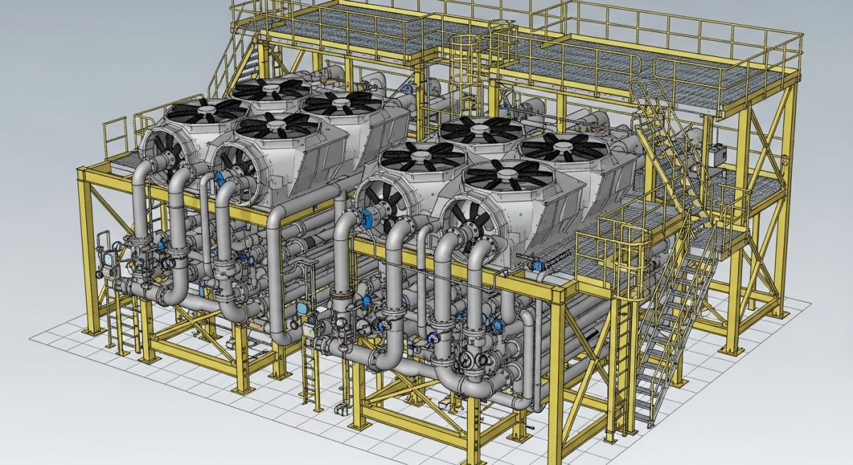
In my 20+ years of piping design, few systems test an engineer’s patience like air-cooled heat exchangers, commonly known as fin-fans. Perched high on top of pipe racks, these massive units experience extreme thermal expansion, structural deflections, and unforgiving nozzle load limits. If you do not design the piping with adequate flexibility, you will warp the header boxes, cause catastrophic flange leaks, or crack the structural steel.
In my experience, successful execution requires a deep understanding of both process requirements and structural mechanics. We are not just routing pipe from point A to point B; we are managing dynamic forces in a highly constrained elevated environment. Let me walk you through the exact layout strategies and stress analysis workflows I use to keep these systems safe, operational, and easy to maintain.
What You Will Learn
- How to layout symmetric inlet and outlet piping manifolds to ensure uniform flow distribution.
- Methods to protect sensitive API 661 nozzles from excessive thermal expansion forces.
- Practical pipe rack structural considerations and maintenance access requirements.
Why Air Cooler Piping Design Demands Flexibility
Air coolers operate at elevated temperatures, often handling hot process vapors directly from fractionating columns. Because these units are mounted on top of structural steel pipe racks, they are subjected to a combination of thermal growth from the piping, thermal growth of the air cooler header box itself, and structural displacements of the rack.
To prevent excessive forces on the nozzles, we must design the piping with high flexibility. This is typically achieved by incorporating expansion loops, offsets, and strategic support configurations. In my experience, relying solely on standard piping guides is a recipe for failure. We must utilize slide plates, such as PTFE or graphite, under the piping supports to minimize frictional forces.
Symmetric Manifold Design for Two-Phase Flow
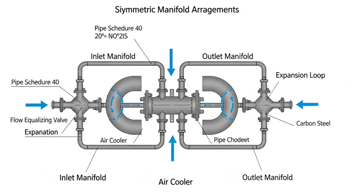
When dealing with condensing services, the inlet piping often carries a two-phase mixture of vapor and liquid. If the piping manifold is asymmetric, the liquid phase will preferentially flow into the branches with lower flow resistance due to gravity and momentum. This maldistribution leads to uneven cooling, thermal stresses within the tube bundles, and reduced heat exchanger efficiency.
To avoid this, I always design the inlet manifold with strict symmetry. This means the piping path from the main header to each individual nozzle must have identical lengths, fittings, and flow resistances. The branches must split symmetrically using equal-leg tees or symmetric Y-fittings.
Calculating Thermal Expansion and Nozzle Loads
The thermal expansion of the piping is calculated using the standard thermal expansion equation:
Delta L = L * alpha * (T_operating – T_ambient)
Where:
• Delta L is the thermal expansion (mm)
• L is the length of the pipe run (m)
• alpha is the mean coefficient of thermal expansion (mm/m/°C)
• T_operating is the maximum operating temperature (°C)
• T_ambient is the minimum ambient design temperature (°C)
The resulting forces and moments at the air cooler nozzles must be checked against the allowable limits defined in API 661 (Table 4). These limits are significantly lower than those for standard shell-and-tube heat exchangers because the header boxes of fin-fans are fabricated from relatively thin plate steel, making them highly susceptible to local deformation.
Standard Nozzle Load Limits for Fin-Fans
The table below outlines the typical allowable nozzle loads for air-cooled heat exchangers in accordance with API 661. These values serve as the baseline for stress analysis using software like CAESAR II.
| Nozzle Size (NPS) | Radial Force Fr (N) | Circumferential Force Fc (N) | Axial Force Fa (N) | Bending Moment Mb (N-m) | Torsional Moment Mt (N-m) |
|---|---|---|---|---|---|
| 4 | 2220 | 1780 | 2670 | 1360 | 1020 |
| 6 | 3340 | 2670 | 4000 | 2710 | 2030 |
| 8 | 4450 | 3560 | 5340 | 4070 | 3050 |
| 10 | 5560 | 4450 | 6670 | 5420 | 4070 |
| 12 | 6670 | 5340 | 8010 | 6780 | 5080 |
Technical Mapping & Specifications Matrix
| Design Parameter | Acronym / Code | Physical Target | Standard Reference |
|---|---|---|---|
| Process Piping Code | ASME B31.3 | Pressure containment and piping stress limits | ASME B31.3 |
| Air-Cooled Exchanger Standard | API 661 / ISO 13706 | Header box design and nozzle load criteria | API Standard 661 |
| Flange Design Standard | ASME B16.5 | Flange ratings and dimensions up to 24 inches | ASME B16.5 |
| Support Friction Coefficient | COF (PTFE) | Friction coefficient less than or equal to 0.10 | Industry Standard |
How to Verify Air Cooler Piping Layouts
Before releasing an air cooler piping design for fabrication, it is critical to perform a comprehensive layout review. This ensures that the physical installation will not interfere with maintenance activities and that the stress analysis assumptions are fully realized in the field.
Design & Field Verification Checklist
-
Symmetric Inlet Manifolding: Verify that the inlet piping split is perfectly symmetric for two-phase services to prevent phase separation.
-
PTFE Slide Plates: Confirm that PTFE or graphite slide plates are specified under all sliding supports on the air cooler deck to minimize friction.
-
Maintenance Clearance: Ensure a minimum of 1.0 meter of clear space is maintained in front of the header box plug sheets for tube cleaning and bundle removal.
-
Spring Hanger Presets: Verify that spring hanger locations and design loads match the CAESAR II stress analysis report exactly.
-
Nozzle Flange Alignment: Check that the piping design allows for easy alignment of the final tie-in flanges without introducing cold-spring forces.
Field Case Study: Real-World Application
The Problem: High Nozzle Loads and Flange Leaks
During commissioning of a hydrocracker unit, a bank of four high-temperature air coolers experienced persistent flange leaks at the inlet nozzles. The operating temperature was 185°C. The original piping design utilized a semi-rigid manifold with standard steel-on-steel guide supports. The thermal expansion of the 12-inch main header pushed the manifold laterally, generating bending moments on the API 661 nozzles that exceeded the allowable limits by over 240%.
The Solution: Redesigning for Flexibility
I was called to the site to resolve the issue. We modeled the entire system in CAESAR II and implemented a two-fold solution. First, we replaced the rigid steel-on-steel supports with PTFE slide plates to drop the friction coefficient from 0.30 to 0.10. Second, we introduced a symmetric U-shaped expansion loop in the main feed line before it reached the manifold. This modification absorbed the thermal growth of the main header and redirected the expansion away from the sensitive nozzles.
The redesigned system was re-analyzed, showing that the nozzle loads dropped to 45% of the API 661 allowable limits. Upon restarting the unit, the flanges remained completely tight, and no further leaks were detected.
Frequently Asked Engineering Questions
Why is symmetric piping critical for air cooler inlets?
How do API 661 nozzle load limits compare to ASME Section VIII?
What is the purpose of using slide plates under air cooler piping supports?
How does tube bundle thermal expansion affect the connected piping?
When should spring hangers be used in air cooler piping systems?
What are the maintenance clearance requirements for fin-fan piping?
Complete Course on
Piping Engineering
Check Now
Key Features
- 125+ Hours Content
- 500+ Recorded Lectures
- 20+ Years Exp.
- Lifetime Access
Coverage
- Codes & Standards
- Layouts & Design
- Material Eng.
- Stress Analysis



