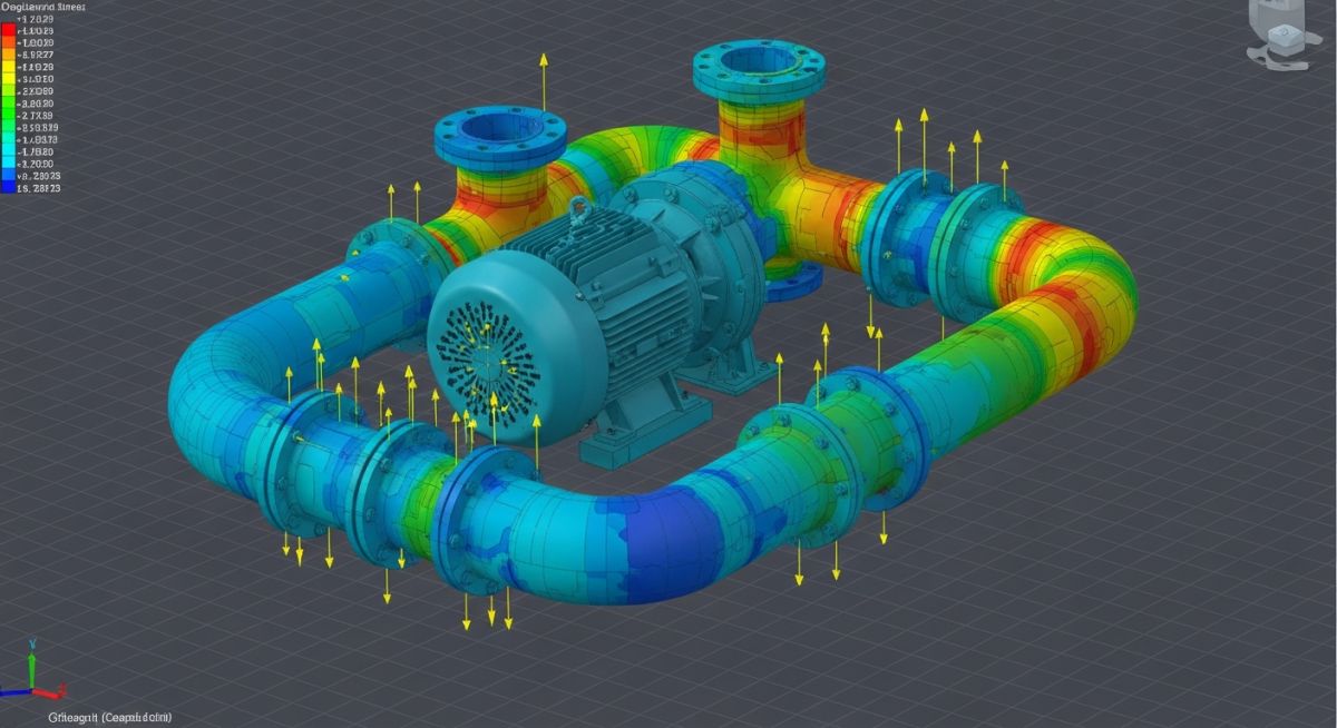
Pump-Piping Alignment Caesar II Stress Analysis Methodology
In my 20+ years of piping engineering, I have seen countless pumps fail prematurely not because of poor pump design, but due to excessive piping loads. When a piping system is bolted to a pump nozzle, any misalignment or thermal expansion forces are directly transferred to the pump casing. This causes shaft misalignment, bearing wear, seal leakage, and sometimes catastrophic casing cracks.
To prevent these field failures, we perform a rigorous pump-piping alignment check using Caesar II. This methodology allows us to simulate the exact physical state of the piping system during bolt-up and operation, ensuring that the forces and moments transferred to the pump nozzles remain well within the strict limits defined by API 610.
Key Engineering Takeaways
- Understand the mathematical modeling of pump nozzles as rigid anchors with thermal displacements.
- Learn how to configure Caesar II load cases specifically for flange alignment checks.
- Master the application of API 610 Table 5 force and moment limits.
- Identify field mitigation techniques when nozzle loads fail code compliance.
- Implement a robust site verification checklist to bridge the gap between stress models and field construction.
How to Perform Pump-Piping Alignment Caesar II Checks
To perform an accurate alignment check in Caesar II, we must carefully model the pump and its connected piping. The pump casing is not a simple anchor; it expands thermally from its centerline anchor point (usually the pump keyway or pin). Therefore, we must calculate the thermal growth of the pump nozzle and input these displacements as boundary conditions in our stress model.
Step 1: Calculating Pump Nozzle Thermal Growth
The thermal displacement of the pump nozzle is calculated using the linear thermal expansion formula:
Delta = L * alpha * (T_operating – T_ambient)
Where:
• L is the distance from the pump foundation anchor point (centerline) to the nozzle face.
• alpha is the coefficient of thermal expansion of the pump casing material.
• T_operating is the operating temperature of the pumped fluid.
• T_ambient is the installation temperature (typically 21 degrees Celsius).
Step 2: Modeling the Pump in Caesar II
In the Caesar II input processor, we model the pump casing as a rigid element from the pump centerline to the suction and discharge nozzles. We apply the calculated thermal displacements (Delta X, Delta Y, Delta Z) at the nozzle node points. Alternatively, we can model the pump casing using a dedicated “Anchor” element with specified thermal growth values.
In my experience, many junior stress engineers make the mistake of modeling pump nozzles as simple, rigid anchors with zero thermal displacement. This oversight can lead to highly inaccurate results, especially for high-temperature pumps (operating above 120 degrees Celsius). Neglecting casing thermal growth can underestimate nozzle loads by up to 40%, leading to unexpected field failures.
Step 3: Defining the Load Cases
To evaluate the pump-piping alignment, we must run a specific set of load cases. These cases must capture the cold installation state, the hot operating state, and the temporary hydrotest state. The standard load cases required for a comprehensive pump alignment check include:
- LC1 (SUS): W + P1 (Sustained load: Weight + Design Pressure)
- LC2 (OPE): W + P1 + T1 + D1 (Operating load: Weight + Pressure + Temperature + Casing Displacement)
- LC3 (EXP): LC2 – LC1 (Expansion range load case)
- LC4 (ALN): W + D1 (Alignment check case: Weight + Casing Displacement without pressure or thermal expansion of the piping, simulating the cold bolt-up state with thermal growth accounted for)
Step 4: Evaluating Nozzle Loads against API 610
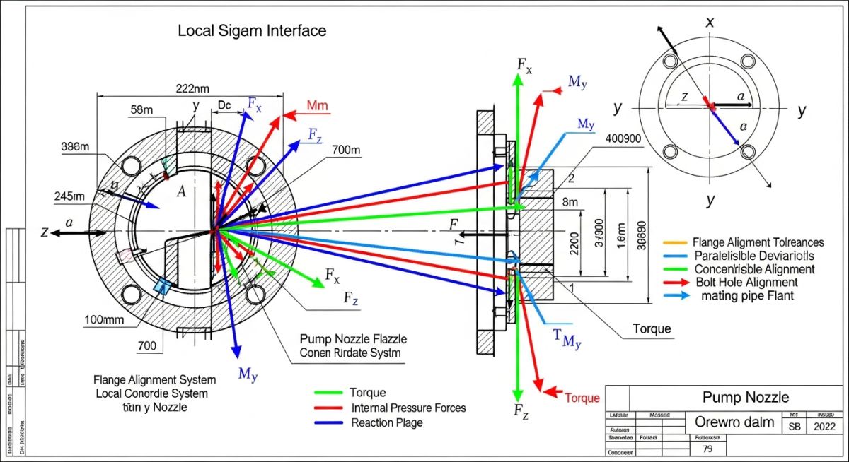
Once the analysis is complete, we extract the forces and moments acting on the pump nozzles from the Caesar II output processor. These loads must be compared against the allowable limits specified in API 610 Table 5. The software features a built-in API 610 evaluation module that automates this comparison, calculating the individual and resultant force/moment ratios.
The resultant force (Fr) and resultant moment (Mr) are calculated using the following equations:
Fr = square_root(Fx^2 + Fy^2 + Fz^2)
Mr = square_root(Mx^2 + My^2 + Mz^2)
The ratio of actual load to allowable load must be less than 1.0 for each individual component, and the combined index (often referred to as the API 610 Annex F criteria) must also be satisfied.
Allowable Nozzle Loads for API 610 Pumps
The table below outlines the standard allowable forces and moments for centrifugal pump nozzles in accordance with API 610 Table 5. These values represent the baseline limits before any coordinate system transformations or material correction factors are applied.
| Nozzle Size (NPS) | Fx (N) | Fy (N) | Fz (N) | Mx (N-m) | My (N-m) | Mz (N-m) |
|---|---|---|---|---|---|---|
| 2 Inch | 710 | 580 | 890 | 460 | 350 | 230 |
| 3 Inch | 1420 | 1160 | 1780 | 950 | 720 | 470 |
| 4 Inch | 2220 | 1820 | 2780 | 1330 | 1000 | 660 |
| 6 Inch | 3110 | 2540 | 3890 | 2300 | 1730 | 1150 |
| 8 Inch | 4890 | 4000 | 6110 | 3530 | 2650 | 1760 |
Technical Mapping of Caesar II Alignment Parameters
| Entity Name | Acronym | Physical Parameter | Standard Reference |
|---|---|---|---|
| Nozzle Node Displacement | DISP | Thermal growth of pump casing (mm) | API 610 Clause 6.5 |
| Rigid Element Weight | RIGID | Weight of pump casing and fluid (kg) | ASME B31.3 Chapter II |
| Flange Alignment Tolerance | ALN-TOL | Maximum allowable gap and offset (mm) | ASME PCC-1 Appendix PE |
| Nozzle Stiffness Matrix | STIFF | Translational and rotational stiffness | API 610 Annex F |
Site Verification Checklist for Flange Alignment
Even the most perfect Caesar II model cannot prevent pump damage if the field construction team forces a misaligned flange onto the pump nozzle. To ensure the integrity of the installation, the field quality control team must execute a physical alignment check. I always recommend using the following checklist before final bolt-up.
Field Flange Alignment Verification Protocol
Verify that the radial offset between the piping flange and the pump nozzle flange does not exceed 1.5 mm. Measure at four locations (90 degrees apart) using a dial indicator or caliper.
Ensure the axial gap between the flange faces matches the gasket thickness plus or minus 0.8 mm. Do not use excessive force or come-alongs to pull the piping to the nozzle.
Measure the gap between the flange faces at four points around the circumference. The difference between the maximum and minimum gap measurements must not exceed 0.4 mm, in compliance with ASME PCC-1.
Confirm that the bolt holes of the mating flanges align perfectly. Bolts must pass through the holes freely by hand without the use of hammers or pry bars.
Mount dial indicators on the pump shaft coupling. Monitor the shaft movement while tightening the flange bolts. If the shaft moves more than 0.05 mm in any direction, stop tightening and realign the piping.
Resolving Failures in Pump-Piping Alignment Caesar II Models
When a Caesar II analysis indicates that the pump nozzle loads exceed the API 610 limits, we must implement design modifications. Simply adding rigid supports is rarely the solution; in fact, it often makes the problem worse by restricting thermal expansion. Instead, we must strategically introduce flexibility or adjust the support configuration.
Field Case Study: Real-World Application
The Problem: High-Temperature Hydrocarbon Pump Nozzle Overload
During a refinery expansion project, a 10-inch suction line on a high-temperature hydrocarbon pump (operating at 280 degrees Celsius) failed the Caesar II alignment check. The initial stress run showed that the bending moment about the Z-axis (Mz) on the suction nozzle was 240% of the allowable limit specified by API 610 Table 5.
The field construction team had already fabricated the piping spool, and any major layout changes would cause significant project delays and cost overruns. The high moment was caused by the thermal expansion of the long vertical run of the suction line pushing directly down onto the pump nozzle.
The Solution: Spring Hanger Optimization and Guide Relocation
To resolve this issue without rerouting the entire piping system, I implemented a two-step mitigation strategy in the Caesar II model:
- Spring Hanger Installation: I replaced the rigid support closest to the pump nozzle with a variable spring hanger. This allowed the vertical piping to expand upward freely, absorbing the thermal expansion instead of transferring the load to the pump nozzle.
- Guide Support Relocation: I relocated a directional guide support three meters further away from the pump nozzle. This increased the flexible leg length of the horizontal run, allowing the piping to bend slightly and absorb the lateral thermal expansion.
After running the optimized Caesar II model, the suction nozzle loads dropped to 68% of the API 610 allowable limits. The field team successfully installed the spring hanger, and the pump has been operating continuously for over five years without a single bearing or seal failure.
Frequently Asked Engineering Questions
Why is API 610 Table 5 used instead of standard ASME B31.3 stress limits for pump nozzles?
How do you model a pump nozzle that is not aligned with the global coordinate axes in Caesar II?
What is the difference between a “cold spring” and a standard alignment check in Caesar II?
Can we exceed API 610 Table 5 nozzle loads if the pump manufacturer approves it?
How does the choice of piping support type affect the pump alignment check?
What is the role of ASME PCC-1 in pump-piping alignment?
Complete Course on
Piping Engineering
Check Now
Key Features
- 125+ Hours Content
- 500+ Recorded Lectures
- 20+ Years Exp.
- Lifetime Access
Coverage
- Codes & Standards
- Layouts & Design
- Material Eng.
- Stress Analysis