Flow Transmitter vs Flow Meter: Key Differences Explained
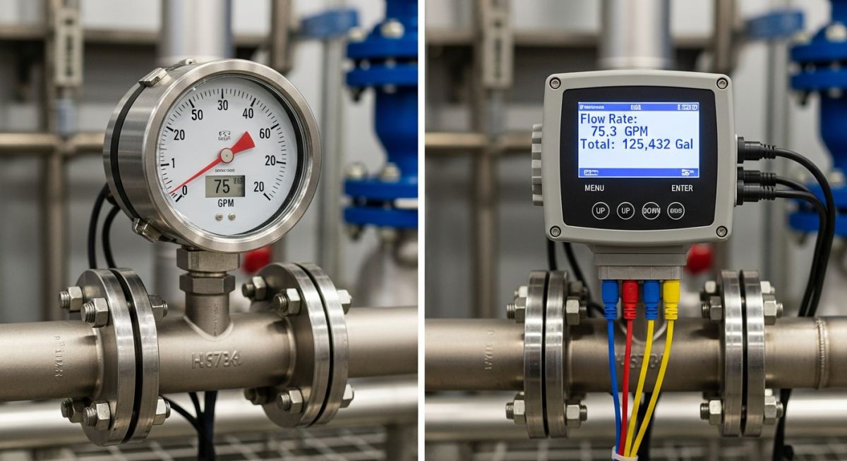
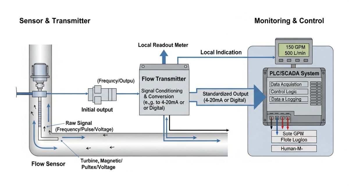
In my 20-plus years of designing piping systems and commissioning process plants, I have seen many junior engineers trip over instrument specifications. The terms “flow meter” and “flow transmitter” are frequently used interchangeably on the field, but doing so in a design office can lead to major procurement errors. A flow meter is the primary element that senses the physical movement of fluid. A flow transmitter is the secondary element that takes that raw physical reading and translates it into a calibrated, long-distance signal like a 4-20mA loop, Modbus, or Foundation Fieldbus.
When you are designing a system that feeds real-time data to a Distributed Control System (DCS) or a Programmable Logic Controller (PLC), you cannot rely on a simple mechanical meter. You need an active transmitter. Understanding this boundary is key to preventing signal attenuation, impedance mismatches, and costly field modifications.
Key Engineering Takeaways
- Signal Output: Flow meters typically provide local mechanical indication or raw pulses, whereas flow transmitters output standardized analog (4-20mA) or digital signals.
- Control Integration: Transmitters are required for closed-loop control systems governed by ISA-5.1 standards.
- Power Requirements: Flow meters can be completely passive (e.g., rotameters), while transmitters require external loop power (typically 24V DC) or line power.
Why Choose Flow Transmitter vs Flow Meter Systems?
To understand the physics, let us look at a classic differential pressure (DP) flow setup. The primary element—such as an orifice plate designed per ASME MFC-3M—creates a localized pressure drop. A simple DP gauge (a flow meter) can display this pressure drop on a dial calibrated in flow units. However, if that pressure drop needs to trigger a control valve three hundred meters away in the control room, a DP transmitter must be piped across the orifice plate.
The Mathematical Foundation of DP Flow Transmitters
The relationship between volumetric flow rate and differential pressure is non-linear. The transmitter must perform a square-root extraction to output a linear signal. The fundamental equation governing this relationship is:
Where:
- Q: Volumetric flow rate (m³/s)
- C_d: Discharge coefficient (dimensionless, typically 0.61 for sharp-edged orifices)
- A_2: Cross-sectional area of the orifice throat (m²)
- delta_P: Measured differential pressure (Pa)
- rho: Fluid density at operating conditions (kg/m³)
- beta: Beta ratio (d/D, ratio of orifice diameter to pipe internal diameter)
Step-by-Step Engineering Calculation Example
Let us calculate the volumetric flow rate for a water line with the following parameters:
- Pipe Internal Diameter (D) = 100 mm (0.1 m)
- Orifice Bore Diameter (d) = 60 mm (0.06 m)
- Beta Ratio (beta) = 0.06 / 0.1 = 0.6
- Fluid Density (rho) = 1000 kg/m³
- Measured Differential Pressure (delta_P) = 25,000 Pa (25 kPa)
- Discharge Coefficient (C_d) = 0.61
First, calculate the orifice area (A_2):
Next, calculate the velocity of approach factor:
Now, substitute these values into our flow equation:
Q = 0.001848 * sqrt(50)
Q = 0.001848 * 7.071 = 0.01307 m³/s
Converting this to hourly flow: 0.01307 * 3600 = 47.05 m³/h. A flow transmitter scales its 4-20mA output so that 4mA represents 0 m³/h and 20mA represents the maximum calibrated range (e.g., 60 m³/h).
Flow Meter vs Flow Transmitter Parameter Comparison
| Parameter | Flow Meter (Primary Element) | Flow Transmitter (Secondary Element) |
|---|---|---|
| Primary Function | Senses physical fluid velocity or mass flow locally. | Converts sensed physical values into standardized electrical signals. |
| Signal Output | Mechanical dial, raw pulses, or local digital display. | 4-20mA, HART, Modbus, Profibus, or Foundation Fieldbus. |
| Power Source | Often passive (fluid kinetic energy) or battery powered. | Active loop power (24V DC) or external line power (110/220V AC). |
| Calibration Scope | Physical calibration of mechanical components. | Electronic zero/span adjustment and square-root extraction. |
| Typical Standards | ASME MFC-14M, ISO 5167 | IEC 61158, ISA-5.1, IEC 60079 (Intrinsically Safe) |
Technical Mapping & Specifications Matrix
| Instrument Type | Acronym | Physical Parameter Measured | Standard Reference |
|---|---|---|---|
| Coriolis Mass Flow Transmitter | FIT (Flow Indicating Transmitter) | Mass Flow, Density, Temperature | ASME MFC-11, ISO 10790 |
| Electromagnetic Flow Meter | FE (Flow Element) | Fluid Velocity (Conductive Liquids) | ASME MFC-16, ISO 20456 |
| Vortex Shedding Transmitter | FT (Flow Transmitter) | Vortex Frequency (Velocity) | ASME MFC-6, ISO 14137 |
How to Verify Flow Instrumentation On-Site
Before powering up any loop, you must verify that the physical installation matches the piping and instrumentation diagrams (P&IDs). A poorly positioned flow element will yield inaccurate data, regardless of how advanced the transmitter is.
Pre-Commissioning Checklist
-
Verify straight run piping requirements (typically 10 diameters upstream, 5 diameters downstream) to eliminate turbulence. -
Confirm flow direction arrow on the meter body matches the actual process fluid flow direction. -
Check that the transmitter enclosure is rated for the area classification (e.g., Class I, Div 1 per NEC 500). -
Perform a loop check to verify that 4mA corresponds to zero flow and 20mA corresponds to the calibrated span limit. -
Ensure the shield wire is grounded at the DCS cabinet side only to prevent ground loops.
Field Case Study: Real-World Application
The Problem: Erratic Control Valve Behavior
During the commissioning of a demineralized water treatment plant, the flow control valve on the feed line was hunting continuously. The design team had specified a turbine flow meter with a local mechanical counter. To get the signal to the PLC, the field technicians had run long, unshielded pulse wires directly from the turbine pickup coil to a high-speed counter card. The 300-meter run picked up massive electromagnetic noise from nearby variable frequency drives (VFDs), causing the PLC to read false high-frequency spikes and cycle the control valve erratically.
The Outcome: Upgrading to an Active Transmitter
I was called to the site to troubleshoot. We immediately replaced the raw pulse-output setup with a dedicated, loop-powered flow transmitter mounted directly on the turbine meter body. The transmitter converted the high-frequency millivolt pulses into a robust, noise-immune 4-20mA analog signal with HART protocol. We also replaced the unshielded wire with a shielded twisted pair. The signal stabilized instantly, the valve hunting stopped, and the plant achieved steady-state operation within hours.
This case highlights why understanding the difference between a raw flow meter and a flow transmitter is critical. A raw sensor signal cannot survive long distances in an industrial environment without active signal conditioning.
Resolving Flow Transmitter vs Flow Meter Selection Issues
Can a flow meter operate without a flow transmitter?
What is a 2-wire vs 4-wire flow transmitter?
How does HART protocol work on a flow transmitter?
Why is square-root extraction needed in DP transmitters?
Which standards govern flow transmitter calibration?
What is the difference between active and passive loops?
===FAQ_BLOCK===
Complete Course on
Piping Engineering
Check Now
Key Features
- 125+ Hours Content
- 500+ Recorded Lectures
- 20+ Years Exp.
- Lifetime Access
Coverage
- Codes & Standards
- Layouts & Design
- Material Eng.
- Stress Analysis

