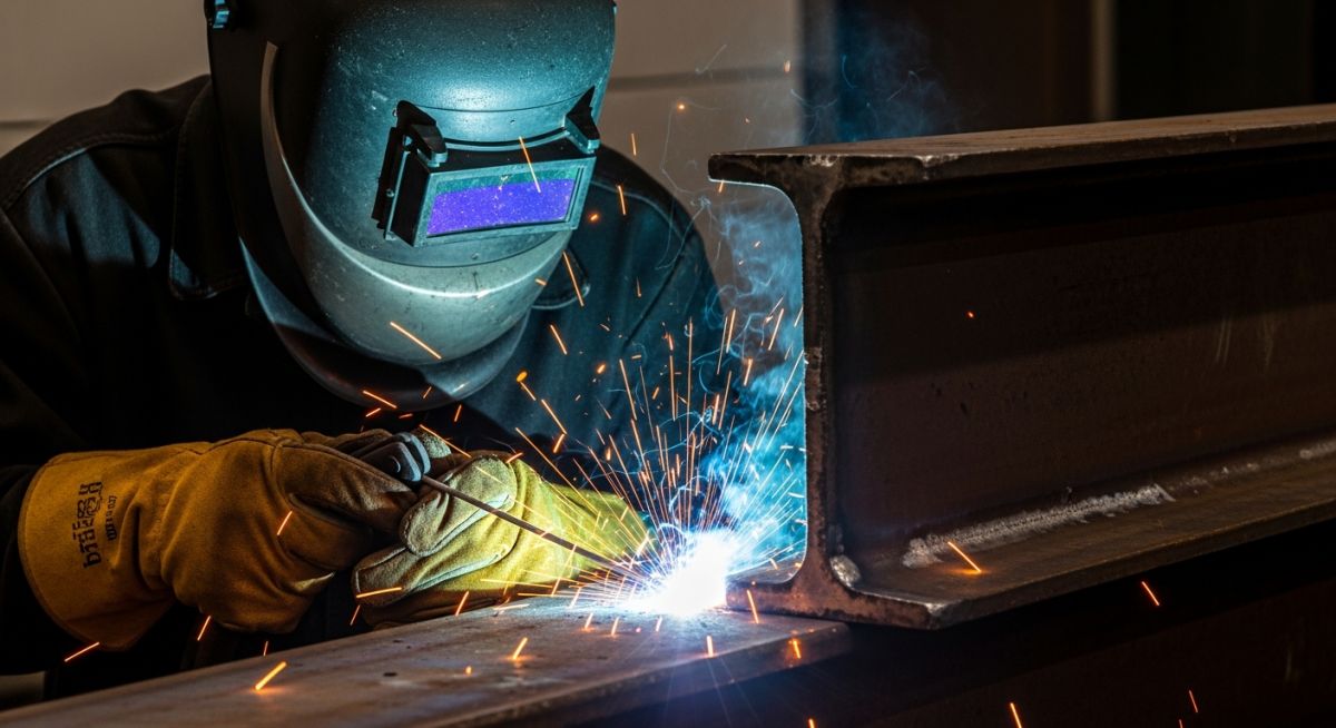
Mastering Industrial Welding Repair Procedures for Structural Integrity
In my 20 years of piping and structural engineering experience, I have seen many field repairs go wrong because teams treated a repair as a simple patch-up job. A welding repair is not just about filling a crack with weld metal; it is a highly engineered process. When you modify a component that has already been subjected to operational stresses, thermal cycles, or environmental degradation, you introduce complex residual stresses and metallurgical changes.
To execute a successful repair, you must understand the parent material’s chemistry, the root cause of the failure, and the exact code requirements. Whether you are working on a high-pressure steam line under ASME B31.3 or a heavy structural column under AWS D1.1, following a qualified, written procedure is your only safeguard against catastrophic failure.
Key Takeaways from This Guide:
- Understand the critical differences between structural and pressure vessel repair codes.
- Learn how to calculate preheat temperatures based on carbon equivalent formulas to prevent cracking.
- Master the step-by-step sequence of defect excavation, preparation, and welding.
- Discover how to implement temper bead welding to avoid post-weld heat treatment when field conditions are restrictive.
How Do We Execute Welding Repair Procedures Safely?
When I plan a repair, the first step is always defect characterization. You cannot repair a defect until you know its boundaries, depth, and orientation. I rely on Non-Destructive Testing (NDT) methods like Ultrasonic Testing (UT) or Magnetic Particle Testing (MT) to map out the damage. Once mapped, the defect must be completely removed.
1. Defect Excavation and Cavity Preparation
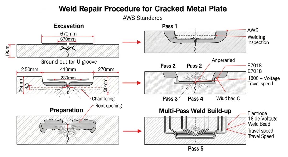
Excavation is typically performed using air carbon arc gouging, grinding, or machining. In my experience, carbon arc gouging is highly efficient but leaves a carbon-rich layer on the surface. This layer must be ground away to bright metal (at least 1 mm of depth) to prevent hard, brittle zones in the subsequent weld. The cavity must have sloped walls (typically 15 to 20 degrees) and generous radii at the bottom to allow proper electrode access and fusion.
2. Calculating Preheat and Heat Input
To prevent hydrogen-induced cracking (HIC), especially in high-strength steels, you must calculate the Carbon Equivalent (CE) of the material. This calculation determines the minimum preheat temperature. I use the standard International Institute of Welding (IIW) formula:
If the CE exceeds 0.40, preheating is mandatory. For example, a steel with a CE of 0.45 typically requires a minimum preheat of 150 degrees Celsius (300 degrees Fahrenheit).
Next, we must control the heat input during welding. High heat input can degrade the toughness of the Heat Affected Zone (HAZ), while low heat input can lead to lack of fusion and rapid cooling cracks. Calculate heat input using this formula:
Never use damp low-hydrogen electrodes (such as E7018) for repairs. Hydrogen is the primary driver of delayed cracking in repairs. Always store these electrodes in holding ovens at 120 to 150 degrees Celsius and limit their atmospheric exposure to under 4 hours. If exposure limits are exceeded, bake them at 350 degrees Celsius for 2 hours before use.
3. Temper Bead Welding Technique
In many field situations, Post-Weld Heat Treatment (PWHT) is impossible due to structural constraints or the presence of internal linings. In these cases, I specify the temper bead welding technique under ASME Section IX (QW-290). This technique uses the heat of subsequent weld passes to temper the HAZ of the previous passes, refining the grain structure and restoring toughness without requiring global thermal treatment.
Preheat and Interpass Temperature Guidelines
The table below outlines the recommended minimum preheat and interpass temperatures based on the Carbon Equivalent (CE) and material thickness. These values are compiled from field experience and standard code recommendations.
| Carbon Equivalent (CE) Range | Thickness Range (mm) | Min Preheat Temp (°C) | Max Interpass Temp (°C) | Post-Heat Requirement |
|---|---|---|---|---|
| Up to 0.35 | All thicknesses | 10 (Ambient) | 250 | None |
| 0.36 to 0.40 | Less than 25 mm | 50 | 250 | Optional |
| 0.36 to 0.40 | 25 mm and above | 100 | 250 | Recommended |
| 0.41 to 0.47 | All thicknesses | 150 | 220 | Mandatory (Hydrogen Bake-out) |
| Above 0.47 | All thicknesses | 200 | 200 | Mandatory (PWHT or Temper Bead) |
Technical Mapping & Specifications Matrix
This matrix maps common industrial defects to their corresponding repair methods, applicable codes, and required inspection techniques.
| Defect Type | Primary Cause | Repair Method | Governing Code | Verification NDT |
|---|---|---|---|---|
| Fatigue Crack | Cyclic loading | Excavate, drill crack tips, weld repair | AWS D1.1 Clause 7 | MT / UT |
| Wall Thinning | Flow-accelerated corrosion | Weld metal buildup (cladding) | ASME PCC-2 Article 2.2 | UT Thickness / RT |
| Hydrogen Cracking | Moisture in weld pool | Complete excavation, preheat, low-H weld | ASME Sec IX / API 570 | PT / UT (after 48 hours) |
| Lamination Defect | Base metal manufacturing flaw | Gouge to clean metal, buttering layer | AWS D1.1 / ASME Sec VIII | UT Straight Beam |
What Is the Pre-Repair Verification Checklist?
Before allowing any welder to strike an arc on a repair job, I walk the site with this checklist. Skipping even one of these steps can lead to a failed repair, requiring you to cut out the entire section and start over, which is incredibly costly.
Field Verification Checklist:
-
Material Identification Verified: Confirm the base metal grade using Mill Test Reports (MTR) or Positive Material Identification (PMI). Never assume the grade of a structural member.
-
Defect Removal Confirmed: Verify that the defect has been completely removed using Liquid Penetrant Testing (PT) or Magnetic Particle Testing (MT) on the excavated cavity.
-
Welder Qualification Checked: Ensure the welder is qualified specifically for the process, position, and material thickness under ASME Section IX or AWS D1.1.
-
Consumables Control: Verify that low-hydrogen electrodes are stored in active holding ovens at the correct temperature and have not exceeded their atmospheric exposure limits.
-
Preheat Equipment Calibrated: Ensure induction heating blankets or tempilstiks (temperature-indicating crayons) are on-site and calibrated to monitor preheat and interpass temperatures.
-
Environmental Protection: Confirm that windbreaks and shelters are in place if the wind speed exceeds 8 km/h (5 mph) for gas-shielded processes.
Why Do Welding Repair Procedures Fail in Fields?
Field Case Study: Real-World Application
During a turnaround at a petrochemical plant, a 50 mm thick 2.25Cr-1Mo steam header was found to have a 150 mm long thermal fatigue crack near a nozzle weld. The plant maintenance team attempted a quick repair by grinding out the crack and welding it using standard SMAW without preheating, assuming the localized heat of the arc would be sufficient. Within 12 hours of completing the weld, a massive transverse crack developed across the entire repaired zone.
I was called to the site to investigate and design a recovery procedure. We determined that the failure was caused by hydrogen-induced cracking due to lack of preheat on a highly hardenable alloy.
Our corrective action plan included:
- Complete excavation of the cracked weld metal plus an additional 3 mm of base metal to remove any micro-cracks.
- A hydrogen bake-out heat treatment at 300°C for 4 hours prior to welding to drive out any dissolved hydrogen.
- Controlled preheating to 250°C using induction heating coils, maintained continuously throughout the welding process.
- Implementation of a temper bead welding sequence using low-hydrogen E9018-B3 electrodes.
- Post-weld heat treatment (PWHT) at 690°C for 2 hours to reduce residual stresses and soften the HAZ.
The subsequent NDT (both UT and MT) showed zero defects, and the header has been operating safely for over five years.
My direct recommendation from this case is clear: never bypass thermal controls on alloy steels. The time you think you are saving by skipping preheat will be lost tenfold when you have to cut out and redo a cracked weld.
Frequently Asked Engineering Questions
Can I use a standard WPS for a welding repair?
What is the purpose of a hydrogen bake-out?
How long should I wait before performing final NDT on a repair?
What is the maximum depth of a repair weld allowed by code?
Can I repair a crack by simply welding over it?
What is the role of ASME PCC-2 in welding repairs?
Complete Course on
Piping Engineering
Check Now
Key Features
- 125+ Hours Content
- 500+ Recorded Lectures
- 20+ Years Exp.
- Lifetime Access
Coverage
- Codes & Standards
- Layouts & Design
- Material Eng.
- Stress Analysis