Centrifugal Compressors: Engineering Design Guidelines and Industrial Applications
In my 20-plus years of commissioning turbomachinery across global petrochemical plants, I have learned that nothing tests an engineer’s grit quite like a high-pressure centrifugal compressor system. These machines are the beating hearts of refineries, gas processing facilities, and large-scale chemical plants. When a centrifugal compressor runs smoothly, the entire plant thrives; when it experiences aerodynamic instability or mechanical failure, the financial and safety implications are staggering.
Throughout my career, I have worked directly with mechanical designers, piping stress analysts, and operations teams to troubleshoot complex vibration, surge, and seal issues. In this comprehensive guide, I will share the practical engineering insights, thermodynamic calculations, and design guidelines that I rely on to ensure these complex machines operate safely, efficiently, and reliably.
Key Engineering Takeaways
- Understand the critical role of the impeller, diffuser, and volute in converting kinetic energy to static pressure.
- Master the thermodynamic equations governing polytropic head, efficiency, and discharge temperature.
- Identify the physical boundaries of compressor operation, specifically the surge and choke limits.
- Implement robust piping design and nozzle load management in compliance with ASME and API standards.
- Apply field-proven pre-commissioning and troubleshooting protocols to prevent catastrophic failures.
How Centrifugal Compressors Optimize Industrial Process Plants
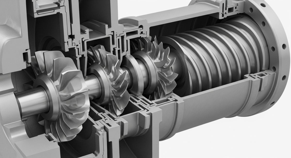
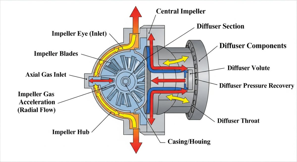
To truly appreciate how these machines function, we must look closely at the energy transfer process. Unlike positive displacement compressors that physically reduce the volume of a gas chamber, centrifugal compressors rely on dynamic principles. Gas enters the compressor through an inlet nozzle and is directed into the eye of a rapidly rotating impeller. The impeller blades accelerate the gas to high velocities, imparting kinetic energy.
As the high-velocity gas leaves the outer diameter of the impeller, it enters a stationary diffuser. The diffuser is a carefully designed divergent passage where the gas slows down. According to Bernoulli’s principle, this reduction in velocity causes a corresponding increase in static pressure. Finally, the gas is collected in a scroll-shaped casing called a volute, which further decelerates the gas and directs it to the discharge nozzle.
Thermodynamic Calculations and Equations
When designing or evaluating a compressor, we must calculate the polytropic head and discharge temperature. Polytropic head represents the energy per unit mass required to compress the gas between the inlet and discharge pressures. The formula for polytropic head is expressed as:
Where:
- Hp = Polytropic head (meters or feet)
- Z = Average gas compressibility factor (dimensionless)
- R = Universal gas constant (8314 J/kmol-K or 1545 ft-lbf/lbm-R)
- T1 = Inlet temperature (Kelvin or Rankine)
- M = Molecular weight of the gas mixture (kg/kmol or lbm/lbmol)
- P1, P2 = Absolute inlet and discharge pressures (kPa or psia)
- n = Polytropic exponent (dimensionless)
The polytropic exponent (n) is related to the specific heat ratio (k = Cp/Cv) and the polytropic efficiency (eta_p) by the following relationship:
In my experience, failing to account for changes in gas composition (and therefore molecular weight and compressibility) is a common root cause of off-design performance issues. If the molecular weight drops below the design value, the compressor will require a higher rotational speed or more stages to achieve the same discharge pressure.
Operating a centrifugal compressor below its minimum stable flow rate triggers a phenomenon known as surge. During surge, the pressure downstream of the compressor exceeds the pressure generated by the impeller, causing a violent, instantaneous reversal of gas flow. This flow reversal occurs cyclically (often 2 to 5 times per second), generating massive axial thrust forces that can destroy thrust bearings, dry gas seals, and impellers within seconds. Always ensure your anti-surge system is designed and calibrated in accordance with API Standard 617 guidelines.
Aerodynamic Boundaries: Surge vs. Choke
The operating envelope of a centrifugal compressor is bounded by two distinct aerodynamic phenomena:
- Surge Limit (Minimum Flow): As flow rate decreases at a constant speed, the pressure ratio increases until the compressor can no longer overcome the system backpressure. The flow separates from the impeller blades, leading to complete flow reversal and severe mechanical vibration.
- Choke Limit / Stonewall (Maximum Flow): As flow rate increases at a constant speed, the velocity of the gas at some point within the compressor (usually the impeller inlet or diffuser throat) reaches sonic velocity (Mach 1). At this point, the flow is choked, and no further increase in volumetric flow rate is physically possible, causing a steep drop in discharge pressure and efficiency.
The following table outlines the typical design parameters, operating limits, and engineering impacts associated with industrial centrifugal compressors designed under API Standard 617.
| Design Parameter | Typical Range | API 617 Recommendation | Engineering Impact |
|---|---|---|---|
| Polytropic Efficiency | 70% to 85% | Maximize within process limits | Directly dictates driver power requirements and discharge temperature. |
| Impeller Tip Speed | 180 to 350 m/s | Limit based on material yield strength | Higher speeds increase head per stage but elevate centrifugal stresses. |
| First Critical Speed | Varies by rotor design | Minimum 15% to 20% separation margin | Prevents destructive resonant vibrations during startup and operation. |
| Discharge Temperature | 80°C to 180°C | Maximum 150°C for standard applications | High temperatures degrade seals, O-rings, and can cause gas polymerization. |
| Surge Margin | 10% to 25% | Minimum 10% flow margin at rated speed | Protects the machine from entering surge during transient process upsets. |
Selecting the correct materials and understanding component functions is vital for long-term reliability. Below is the technical mapping matrix for major centrifugal compressor components.
| Component / Entity | Material Specification | Key Function | Standard Reference |
|---|---|---|---|
| Impeller | 17-4 PH Stainless Steel, Titanium, or Low-Alloy Steel | Imparts kinetic energy to the process gas via centrifugal force. | ASTM A564 / API 617 |
| Rotor Shaft | AISI 4340 or 4140 Forged Alloy Steel | Transmits mechanical torque from the driver to the impellers. | ASTM A293 / API 617 |
| Dry Gas Seals | Silicon Carbide faces with Hastelloy springs | Prevents process gas from escaping to the atmosphere along the shaft. | API Standard 682 |
| Journal Bearings | Tilt-pad type with Babbitt lining | Supports radial rotor loads and suppresses subsynchronous vibration. | API 617 / ISO 7919 |
| Casing | Cast Steel (ASTM A216) or Forged Carbon Steel | Contains internal pressure and supports stationary internals. | ASME Section VIII / API 617 |
Pre-Commissioning Checklist for Centrifugal Compressors
Before introducing hydrocarbons or spinning the rotor, a rigorous field verification protocol must be executed. In my experience, skipping even a single check on this list can lead to catastrophic mechanical damage during the initial startup sequence.
Field Verification Checkpoints
-
Lube Oil System Flushing: Verify that the lube oil system has been flushed to meet ISO 4406 cleanliness standards (typically 16/14/11 or better) and that all run-in filters are clean.
-
Cold and Hot Alignment: Perform laser alignment between the compressor and driver shafts. Verify that cold alignment offsets account for thermal growth calculations in accordance with API RP 686.
-
Piping Strain Verification: Install dial indicators on the compressor nozzles and unbolt the suction and discharge piping. Nozzle movement must not exceed 0.05 mm (0.002 inches) to prevent casing distortion.
-
Dry Gas Seal Gas Quality: Confirm that the seal gas supply is clean, dry, and superheated by at least 20°C above its dew point to prevent liquid condensation across the seal faces.
-
Anti-Surge Valve (ASV) Stroke Test: Verify that the anti-surge control valve strokes from fully closed to fully open in less than 1.5 to 2.0 seconds to ensure rapid response during process upsets.
-
Rotor Solo Run: Conduct a solo run of the driver (steam turbine, gas turbine, or electric motor) to verify rotation direction, speed control, and overspeed trip settings.
-
Instrumentation Calibration: Calibrate all radial vibration probes, axial displacement probes, and bearing thermocouples, verifying correct alarm and trip setpoints in the machine monitoring system.
Field Case Study: Real-World Application
During the commissioning of a multi-stage, high-pressure natural gas injection compressor in a Middle Eastern gas plant, the machine experienced severe subsynchronous vibration as it approached 85% of its design speed. The vibration levels at the non-drive end radial probes spiked from a normal 15 microns to over 65 microns within seconds, triggering an automatic emergency shutdown (ESD).
The project team was under immense pressure, as every day of delay cost the operator hundreds of thousands of dollars. Initial theories blamed rotor unbalance, but my analysis of the vibration spectrum showed a dominant frequency at 42% of the running speed, which is a classic signature of aerodynamic excitation or oil whirl.
We conducted a thorough investigation of the internal clearances and the labyrinth seal design. It was discovered that high-pressure gas swirling in the balance piston labyrinth seal was generating a destabilizing cross-coupled aerodynamic force, causing rotor dynamic instability (commonly known as rotordynamic swirl).
To resolve the issue, we implemented two corrective actions:
- Replaced the standard labyrinth balance piston seal with a shunt-inlet swirl brake design to counteract the tangential gas velocity.
- Optimized the tilt-pad journal bearing clearances and increased the oil supply temperature slightly to adjust the oil film stiffness.
Upon restart, the compressor was successfully ramped up to 100% speed. The subsynchronous vibration was completely eliminated, and radial vibration levels remained below 12 microns across the entire operating envelope.
My direct recommendation for any high-pressure gas application is to perform a rigorous rotordynamic stability analysis during the design phase. Ensure that the compressor manufacturer includes swirl brakes or abradable honeycomb seals on the balance piston if the gas density exceeds 40 kg/m³.
Centrifugal Compressors: Frequently Asked Engineering Questions
What is the primary difference between a centrifugal compressor and an axial compressor?
Why is API Standard 617 so important for centrifugal compressors?
How does gas molecular weight affect centrifugal compressor performance?
What are dry gas seals and why are they preferred over wet seals?
What is the function of a guide vane (IGV) in a centrifugal compressor?
How do piping thermal expansion loads affect compressor alignment?
Complete Course on
Piping Engineering
Check Now
Key Features
- 125+ Hours Content
- 500+ Recorded Lectures
- 20+ Years Exp.
- Lifetime Access
Coverage
- Codes & Standards
- Layouts & Design
- Material Eng.
- Stress Analysis