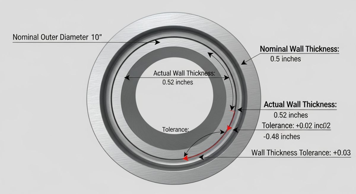
What is Mill Tolerance and How Does It Affect Piping Design?
In my 20 plus years of piping engineering experience, I have seen brilliant designs on paper turn into catastrophic field failures simply because a junior engineer forgot one fundamental truth: steel mills do not manufacture perfect pipes. When you specify a pipe with a 10-millimeter wall thickness, the pipe that arrives on your job site will rarely measure exactly 10 millimeters.
This inherent manufacturing variation is what we call mill tolerance. It is not a defect; it is a legally and technically permitted deviation defined by standards organizations like the American Society for Testing and Materials (ASTM) and the American Society of Mechanical Engineers (ASME). If you do not account for this under-tolerance during your initial wall thickness calculations, your piping system may operate with a dangerously low safety factor, risking localized yielding or rupture under high pressures.
Key Engineering Takeaways
- Seamless carbon steel pipes (such as ASTM A106 Grade B) typically carry a standard mill tolerance of minus 12.5 percent.
- Design codes like ASME B31.3 and ASME B31.1 mandate that the nominal wall thickness must be selected based on the minimum calculated thickness divided by the tolerance factor.
- Mill tolerance applies to both wall thickness and outer diameter, though wall thickness variation poses the greatest risk to pressure containment.
- Ultrasonic thickness testing at the receiving yard is the only reliable way to verify the actual physical wall thickness of delivered piping spools.
Why Mill Tolerance Matters in Piping Design
When designing a pressurized piping system, we must calculate the minimum required wall thickness to prevent hoop stress failure. The standard formula under ASME B31.3 Section 304.1.2 defines the pressure design thickness (t) as:
Where:
P = Internal design gage pressure
D = Outside diameter of the pipe
S = Allowable stress value for the material at design temperature
E = Quality factor
W = Weld joint strength reduction factor
Y = Coefficient from Table 304.1.1
However, this calculated value (t) only represents the absolute minimum thickness required to contain the pressure. To find the nominal wall thickness (t_nom) that you must specify in your procurement documents, you must add mechanical allowances (such as thread depth or grooving), corrosion/erosion allowances (c), and then divide by the mill tolerance factor.
For a standard seamless pipe with a minus 12.5 percent mill tolerance, the formula to determine the minimum ordered nominal wall thickness is:
If you fail to divide by 0.875, and the mill delivers a pipe that is 12.5 percent thinner than nominal, your actual wall thickness will fall below the code-mandated minimum pressure design thickness. This is a direct violation of ASME codes and invites localized stress concentrations, accelerated corrosion failure, and potential liability.
Never assume that welded pipes and seamless pipes share the same mill tolerance. While seamless pipes are typically subject to a minus 12.5 percent tolerance due to the rotary piercing process, welded pipes often have much tighter tolerances (typically minus 0.3 millimeters or minus 10 percent depending on the specific ASTM standard). Always verify the exact manufacturing standard before running your calculations.
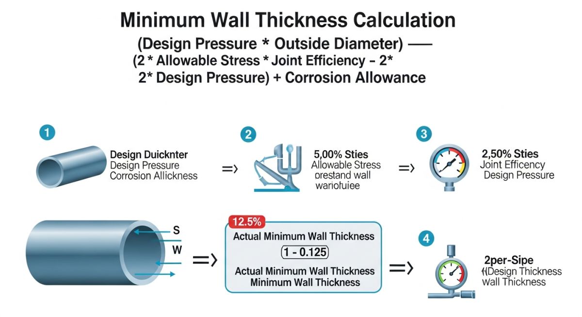
Let us look at a practical example. Suppose your pressure design calculation requires a minimum wall thickness (t) of 6.0 millimeters, and your process fluid requires a corrosion allowance (c) of 1.5 millimeters. The total required thickness before mill tolerance is 7.5 millimeters.
If you are using seamless ASTM A106 Grade B pipe, you must divide 7.5 millimeters by 0.875, which yields 8.57 millimeters. Looking at standard pipe schedules (ASME B36.10M), a 4-inch Schedule 40 pipe has a nominal wall thickness of 6.02 millimeters (insufficient), while a Schedule 80 pipe has a nominal wall thickness of 8.56 millimeters. In this scenario, you would be forced to select Schedule 80 or negotiate a custom wall thickness with the mill to ensure code compliance.
Standard Mill Tolerance Values for Piping
To simplify your design process, I have compiled the standard mill tolerances for the most common piping materials used in industrial plants today. These values are sourced directly from the respective ASTM specifications.
| ASTM Standard | Material Type | Manufacturing Method | Under-Tolerance Limit | Over-Tolerance Limit |
|---|---|---|---|---|
| ASTM A106 | Carbon Steel | Seamless | -12.5% | +15.0% |
| ASTM A53 | Carbon Steel | Seamless / Welded | -12.5% | +15.0% |
| ASTM A312 | Stainless Steel | Seamless (t < 3/8″) | -12.5% | +20.0% |
| ASTM A312 | Stainless Steel | Welded (All sizes) | -12.5% | +15.0% |
| ASTM A335 | Alloy Steel | Seamless (t >= 5/16″) | -12.5% | +22.5% |
Technical Mapping & Specifications Matrix
This matrix maps the relationship between manufacturing standards, design codes, and the physical parameters that must be verified during the engineering phase.
| Design Code | Verification Parameter | Primary Inspection Tool | Acceptance Criteria Reference |
|---|---|---|---|
| ASME B31.3 | Minimum Wall Thickness (t_min) | Ultrasonic Thickness Gauge (UT) | ASME B31.3 Clause 304.1.2 |
| ASME B31.1 | Power Piping Wall Thinning | UT Grid Mapping | ASME B31.1 Clause 104.1.2 |
| ASME Section VIII Div 1 | Pressure Vessel Shell Thickness | Laser Profilometry / Calipers | UG-16(b) Minimum Thickness |
How to Verify Mill Tolerance on Site
When pipes arrive at the construction site or fabrication shop, you should never assume they meet the nominal thickness specified in the purchase order. In my practice, I enforce a strict receiving inspection protocol to catch under-thickness materials before they are welded into spools.
Field Inspection Checklist for Pipe Wall Thickness
-
Verify Mill Test Reports (MTRs): Cross-reference the heat numbers stamped on the pipes with the supplied MTRs. Ensure the reported minimum wall thickness is within the ASTM standard limit (e.g., not less than 87.5% of nominal for ASTM A106).
-
Perform Ultrasonic Thickness (UT) Testing: Calibrate the UT gauge using a calibration block of the same material grade. Take measurements at four quadrants (12, 3, 6, and 9 o’clock positions) on both ends of the pipe.
-
Check Ovality and Outer Diameter: Use a pi-tape or vernier calipers to measure the outer diameter. Ensure the ovality (difference between maximum and minimum OD) does not exceed the limits specified in ASME B36.10M.
-
Document and Flag Non-Conformances: If any single point measurement falls below the calculated minimum wall thickness (t_min), quarantine the pipe immediately and issue a Non-Conformance Report (NCR) to the vendor.
Field Case Study: Real-World Application
The Problem: High-Pressure Steam Line Bulging
During a pre-commissioning hydrotest at a combined-cycle power plant, a 12-inch high-pressure steam line (designed to ASME B31.1) exhibited localized bulging near a long-radius elbow. The design team had specified ASTM A106 Grade B seamless pipe with a nominal wall thickness of 10.31 millimeters (Schedule 40).
Upon investigation, I discovered that the design engineer had calculated the required pressure design thickness as 9.1 millimeters. They assumed that because 10.31 millimeters is greater than 9.1 millimeters, the pipe was safe. However, they failed to apply the 12.5 percent mill tolerance. The actual pipe delivered from the mill had a wall thickness of only 9.02 millimeters at the outer radius of the bend—well below the code-mandated minimum.
The Outcome: Remediation and Redesign
We immediately halted the hydrotest and quarantined the affected piping spool. To resolve the issue without delaying the project schedule, we replaced the Schedule 40 spools with Schedule 80 spools (nominal wall thickness of 15.09 millimeters). This provided a comfortable safety margin, even when accounting for the 12.5 percent mill tolerance and localized thinning from the pipe bending process.
I also implemented a mandatory design review step in our engineering office: all stress analysis models in CAESAR II must have the “Use Nominal Thickness” option unchecked, forcing the software to run stress checks using the minimum wall thickness (nominal minus 12.5 percent).
This case study proves that mill tolerance is not a theoretical academic concept. It is a physical reality that can lead to catastrophic structural failures, project delays, and millions of dollars in rework if ignored during the early engineering phases.
Understanding Mill Tolerance in Daily Practice
What is the standard mill tolerance for ASTM A106 Grade B seamless pipe?
How do you calculate minimum wall thickness including mill tolerance?
Does mill tolerance apply to the outer diameter of a pipe?
Why do welded pipes have different tolerances than seamless pipes?
How does CAESAR II handle mill tolerance in stress analysis?
Can you order pipes with zero or positive-only mill tolerance?
Complete Course on
Piping Engineering
Check Now
Key Features
- 125+ Hours Content
- 500+ Recorded Lectures
- 20+ Years Exp.
- Lifetime Access
Coverage
- Codes & Standards
- Layouts & Design
- Material Eng.
- Stress Analysis