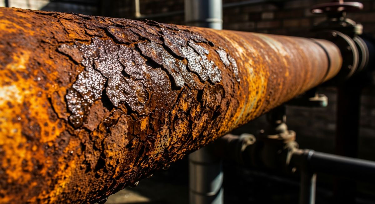
How to Identify and Prevent Rusting Pipes in Industrial Systems
Over my 20 years in piping engineering, I have walked into countless process plants where the silent killer of steel—corrosion—was treated as an afterthought until a catastrophic line rupture occurred. Rusting pipes are not just an aesthetic nuisance; they represent a progressive mechanical degradation that directly threatens plant safety, operational uptime, and structural integrity. In this guide, I will share the exact field methodologies, chemical principles, and engineering standards I use to diagnose, prevent, and treat pipe corrosion before it leads to costly unscheduled shutdowns.
Key Engineering Takeaways
- Understand the electrochemical cell dynamics that drive localized pitting and uniform wall loss.
- Learn how to calculate remaining pipe life and minimum allowable wall thickness per ASME B31.3.
- Identify the differences between uniform corrosion, galvanic action, and microbiologically influenced corrosion (MIC).
- Implement robust prevention strategies including cathodic protection, chemical inhibition, and advanced barrier coatings.
- Master the field inspection techniques required by API 570 to verify system integrity.
The Chemical Mechanisms Behind Rusting Pipes
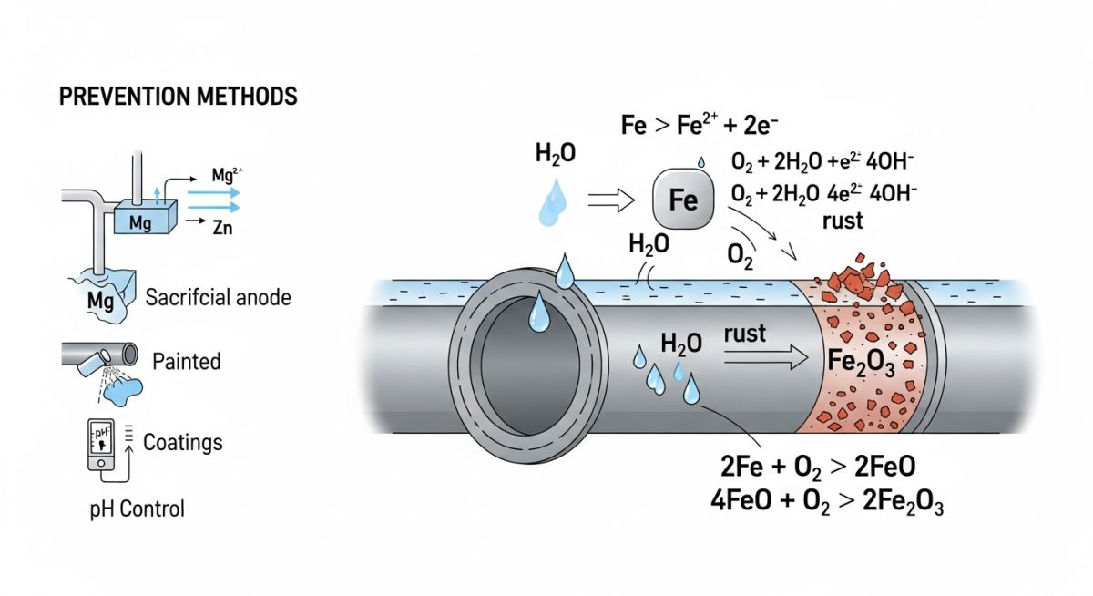
To effectively mitigate corrosion, we must first look at the underlying electrochemistry. Rusting is not a simple chemical reaction; it is an electrochemical process that requires four distinct components: an anode, a cathode, an electrolyte, and a metallic return path. If you remove any of these four elements, the corrosion process stops entirely.
At the anodic site, iron is oxidized, releasing electrons into the bulk metal:
These electrons travel through the pipe wall to the cathodic site, where they react with dissolved oxygen and water to form hydroxyl ions:
The ferrous ions (Fe2+) and hydroxyl ions (OH-) combine in the electrolyte to form ferrous hydroxide, which further oxidizes in the presence of oxygen to produce hydrated iron oxide, commonly known as rust:
Calculating Corrosion Rates and Remaining Life
In my practice, I rely on quantitative data to make run-or-repair decisions. We calculate the corrosion rate using weight-loss coupon data or ultrasonic thickness (UT) measurements over time. The standard formula for corrosion rate is:
Where:
W = Weight loss in grams
K = Constant (87600 for mm/year, or 3450000 for mils/year)
D = Metal density in g/cm3 (7.87 for carbon steel)
A = Exposed surface area in cm2
T = Exposure time in hours
ASME B31.3 Minimum Wall Thickness Verification
To determine if a rusting pipe is safe for continued operation, we must compare its actual measured wall thickness against the minimum design wall thickness required by ASME B31.3:
Where the pressure design thickness (t) is calculated as:
Where:
P = Internal design gage pressure (MPa or psi)
D = Outside diameter of the pipe (mm or inches)
S = Allowable stress value for the material at design temperature (MPa or psi)
E = Quality factor (from ASME B31.3 Table A-1A or A-1B)
W = Weld joint strength reduction factor
Y = Coefficient from ASME B31.3 Table 304.1.1
c = Mechanical allowances (thread depth) plus corrosion and erosion allowances
Evaluating Material Resistance to Prevent Rusting Pipes
Selecting the correct material is the first line of defense against premature piping failures. The table below outlines typical corrosion rates and service limits for common piping materials exposed to aerated water systems.
| Material Grade | Corrosion Rate (mm/yr) | Recommended Service Limits | Applicable Standard |
|---|---|---|---|
| Carbon Steel (ASTM A106 Gr. B) | 0.12 to 0.50 | Non-corrosive hydrocarbons, dry utility air, closed-loop treated water | ASTM A106 |
| Galvanized Steel (ASTM A53 Gr. B) | 0.02 to 0.08 | Potable water, low-pressure utility water, open-loop cooling towers (limited) | ASTM A53 |
| Stainless Steel (ASTM A312 TP316L) | < 0.005 | Demineralized water, corrosive chemicals, high-purity steam condensate | ASTM A312 |
| Copper-Nickel (ASTM B466 C70600) | 0.01 to 0.03 | Seawater cooling lines, marine piping, high-salinity process water | ASTM B466 |
This matrix maps the core technical entities, structural acronyms, and physical parameters associated with pipe corrosion and prevention.
| Entity / Acronym | Technical Parameter | Physical Significance | Reference Standard |
|---|---|---|---|
| MIC | Microbiologically Influenced Corrosion | Accelerated localized pitting caused by sulfate-reducing bacteria (SRB) | NACE TM0194 |
| PREN | Pitting Resistance Equivalent Number | Formula-based index indicating pitting resistance of stainless steels | ISO 15156 |
| CUI | Corrosion Under Insulation | Severe external rusting hidden beneath thermal insulation jackets | NACE SP0198 |
| DFT | Dry Film Thickness | Thickness of protective coating layer applied to prevent oxidation | SSPC-PA 2 |
Field Inspection Protocols for Rusting Pipes
I have developed this checklist over years of conducting field audits. It provides a structured approach to identifying and evaluating corrosion issues before they escalate into mechanical failures.
API 570 Piping Inspection Checklist
Inspect insulation cladding for water entry points, damage, or bulging. Pay special attention to piping operating between -4°C (25°F) and 175°C (350°F).
Measure wall thickness at high-turbulence areas, including elbows, tees, reducer sections, and downstream of control valves.
Check pipe-to-support interfaces where moisture can pool. Look for crevice corrosion and wear on protective pads.
Verify that structure-to-soil potential readings meet the -850 mV copper/copper sulfate reference electrode criterion per NACE SP0169.
Monitor pH, dissolved oxygen levels, and conductivity. Ensure corrosion inhibitor residuals are within specified operating limits.
Field Case Study: Real-World Application
The Problem: Severe CUI on a 10-Inch Cooling Water Line
During a scheduled turnaround at a chemical processing plant, my team discovered severe external corrosion on a 10-inch carbon steel cooling water line. The line was insulated for process temperature control. Moisture had penetrated the aluminum cladding, trapping water against the pipe wall. Ultrasonic testing revealed that the nominal wall thickness of 9.27 mm (Schedule 40) had degraded to 3.10 mm in localized areas, falling well below the ASME B31.3 minimum allowable thickness of 4.20 mm for the operating pressure of 2.4 MPa.
The Outcome: Engineering Remediation and Prevention
We immediately isolated the line and replaced the severely corroded sections with new carbon steel pipe. To prevent future failures, we applied a high-performance, two-coat thermal spray aluminum (TSA) coating system to the pipe exterior. We replaced the traditional calcium silicate insulation with non-wicking aerogel insulation and installed moisture-monitoring ports along the cladding. After three years of continuous operation, follow-up UT scans showed zero wall loss, saving the plant an estimated 180,000 in unplanned shutdown costs.
My direct recommendation for any insulated carbon steel system operating in a humid environment is to avoid cheap barrier coatings. Invest in high-build epoxy phenolic coatings or thermal spray aluminum. The upfront cost is easily offset by the extended service life and the elimination of catastrophic failures.
Frequently Asked Engineering Questions
What are the primary causes of rusting pipes in industrial water systems?
How does dissolved oxygen influence the rate of pipe corrosion?
What is the difference between uniform corrosion and pitting corrosion?
How does cathodic protection prevent rusting pipes?
What standards govern the inspection of corroded piping systems?
Can chemical inhibitors stop internal pipe rusting?
Complete Course on
Piping Engineering
Check Now
Key Features
- 125+ Hours Content
- 500+ Recorded Lectures
- 20+ Years Exp.
- Lifetime Access
Coverage
- Codes & Standards
- Layouts & Design
- Material Eng.
- Stress Analysis
