Table of Contents
What is the Difference Between Pump and Compressor Systems?
In my 20+ years of piping engineering, I have walked through dozens of hydrocarbon processing facilities, chemical plants, and offshore platforms. One of the most common design errors I observe among junior engineers is a fundamental misunderstanding of how fluid properties dictate the mechanical design of rotating equipment. When you are designing a piping system, treating a gas compressor like a high-pressure liquid pump is a recipe for catastrophic field failure.
Pumps and compressors are the workhorses of the industrial world, yet they operate on entirely different thermodynamic and physical principles. While both are designed to increase the energy level of a fluid, the physical state of that fluid—liquid versus gas—changes everything from the casing thickness and nozzle loading to the control systems and safety relief configurations.
Key Engineering Takeaways
- Fluid Compressibility: Pumps handle liquids with negligible density changes, whereas compressors handle highly compressible gases where density increases drastically with pressure.
- Thermodynamic Behavior: Gas compression generates substantial heat, requiring interstage cooling, while liquid pumping results in minimal temperature rise.
- Design Standards: Pumps are governed by standards like API 610 and ASME B73.1, while compressors follow API 617, API 618, or API 619 depending on their mechanical configuration.
- Control Philosophies: Pumps rely on minimum flow bypass valves to prevent overheating, whereas compressors require sophisticated anti-surge systems to prevent destructive flow reversals.
Understanding the Difference Between Pump and Compressor Units
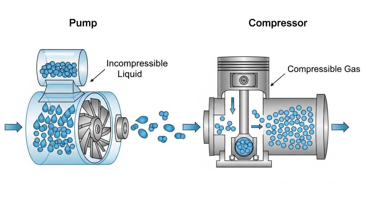
To truly grasp the mechanical divergence, we must look at the governing equations of fluid dynamics. For an incompressible liquid passing through a pump, the density remains constant. The hydraulic power required is directly proportional to the volumetric flow rate and the differential head:
Where:
Q = Volumetric flow rate (m3/h)
rho = Fluid density (kg/m3)
g = Acceleration due to gravity (9.81 m/s2)
H = Total dynamic head (m)
Because the liquid density is constant, the volumetric flow rate entering the pump is identical to the volumetric flow rate exiting the pump. The mechanical work is spent entirely on overcoming elevation, friction, and system pressure.
In contrast, a compressor handles gases where density is a function of pressure and temperature, governed by the real gas law (PV = ZnRT). The work of compression is a thermodynamic process, typically modeled as isentropic or polytropic. The isentropic power required for a compressor is calculated as:
Where:
k = Ratio of specific heats (Cp/Cv)
m = Mass flow rate (kg/s)
R = Universal gas constant (8.314 kJ/kmol-K)
T1 = Suction temperature (K)
M = Molecular weight of the gas
P1, P2 = Absolute suction and discharge pressures (kPa)
This thermodynamic relationship highlights why gas compression generates extreme temperatures. As the gas volume is forced to decrease, the molecular collisions increase, converting mechanical work into thermal energy. If this heat is not managed via interstage coolers, the high temperatures will destroy mechanical seals, degrade lubricants, and exceed the design limits of the piping materials.
Mechanical Design and Construction Differences
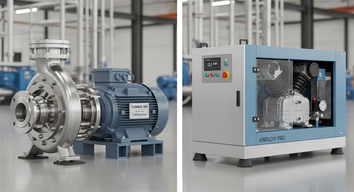
The physical construction of these machines reflects their operating conditions. Pump casings are designed to contain high pressures but are generally compact because liquids are dense and require smaller volumetric spaces. Centrifugal pump impellers are designed to accelerate the liquid radially, converting kinetic energy to static pressure in the volute.
Compressors, especially multi-stage centrifugal or reciprocating units, are massive by comparison. Because gas has a low density, huge volumes must be processed to achieve significant mass flow. Multi-stage centrifugal compressors require complex impellers, diffusers, and return channels. Reciprocating compressors utilize large cylinders, pulsation dampeners, and heavy flywheels to smooth out the pressure pulses inherent in positive displacement gas compression.
Analyzing the Difference Between Pump and Compressor Performance
To assist in equipment selection and piping layout design, I have compiled the primary mechanical and operational differences into a direct comparison matrix. This table highlights the parameters that must be evaluated during the front-end engineering design (FEED) phase of a project.
| Parameter | Industrial Pumps | Industrial Compressors |
|---|---|---|
| Fluid Phase | Liquid only (tolerates minimal entrained gas, typically less than 2%) | Gas or vapor only (liquids must be completely removed via suction scrubbers) |
| Fluid Compressibility | Incompressible (density remains constant under pressure) | Highly compressible (density increases proportionally with pressure) |
| Temperature Change | Negligible temperature rise across the machine | Significant temperature rise (requires intercoolers and aftercoolers) |
| Primary Design Standards | API 610, ASME B73.1, ISO 5199 | API 617, API 618, API 619, ASME PTC 10 |
| Critical Operational Risk | Cavitation (vaporization of liquid due to low suction pressure) | Surge (aerodynamic instability causing violent flow reversal) |
| Typical Pressure Ratios | Can be extremely high in multi-stage units (up to 100+ bar differential) | Limited per stage (typically 1.5 to 4.0 to control discharge temperature) |
Technical Mapping & Specifications Matrix
The following matrix maps the core technical entities, structural acronyms, and physical parameters associated with both equipment types. This is an invaluable reference for piping stress analysts and process engineers.
| Entity / Acronym | Technical Definition | Applicable Equipment | Reference Standard |
|---|---|---|---|
| NPSHa / NPSHr | Net Positive Suction Head Available vs. Required to prevent cavitation | Pumps (Centrifugal) | API 610 |
| ASV / Anti-Surge | Anti-Surge Valve used to recycle gas to prevent aerodynamic stall | Compressors (Centrifugal) | API 617 |
| Pulsation Dampener | Vessel designed to absorb pressure pulses in positive displacement machines | Reciprocating Pumps & Compressors | API 674 / API 618 |
| Suction Scrubber | Separation vessel to remove liquid droplets before gas enters the machine | Compressors (All types) | ASME Section VIII |
Field Verification for Rotating Equipment Installations
Before any pump or compressor is energized for commissioning, a rigorous field verification must be executed. In my experience, skipping these checks is the leading cause of premature seal failure, bearing damage, and piping cracks during plant startup.
Site Verification Checkpoints
-
Piping Alignment (Shaft Runout): Verify that the final piping connections do not impose excessive nozzle loads on the equipment casing. Dial indicators or laser alignment tools must show less than 0.05 mm of movement at the coupling when the flanges are bolted up.
-
Suction Strainer Installation: Ensure temporary cone strainers (witch’s hats) are installed in the suction piping to catch construction debris. For compressors, verify the mesh size is fine enough to protect the impellers without causing excessive pressure drop.
-
Auxiliary Piping Systems: Confirm that seal flush plans (e.g., API Plan 11, 32, or 53B for pumps) and dry gas seal systems (for compressors) are fully tubed, pressure tested, and commissioned with the correct utility fluids.
-
Pulsation Dampener Pre-charge: For reciprocating pumps and compressors, verify that the pulsation dampener nitrogen pre-charge pressure is calibrated based on the actual operating suction and discharge pressures.
-
Anti-Surge / Minimum Flow Loop: Verify that the anti-surge valve (compressors) or minimum flow bypass valve (pumps) is calibrated, stroke-tested, and fails in the fully open position to protect the machine.
Field Case Study: Real-World Application
The Problem: Two-Phase Flow in a Hydrocarbon Transfer Pump
During the commissioning of a refinery expansion project, a heavy gas oil transfer pump experienced severe vibration, erratic discharge pressure, and mechanical seal failure within 48 hours of startup. The design team had selected an API 610 centrifugal pump for the service. However, they failed to account for the fact that the suction fluid contained dissolved light hydrocarbons that flashed into vapor as the fluid experienced a pressure drop through the suction piping and pump inlet nozzle.
The pump was effectively trying to act as a compressor, compressing the flashed gas pockets. Because centrifugal pumps are mechanically incapable of compressing gas phases, the vapor bubbles collapsed violently against the impeller blades (cavitation), causing severe mechanical damage and shaft deflection.
The Outcome: Redesign and Process Modification
As the lead piping consultant brought in to resolve the crisis, I performed a detailed hydraulic analysis of the suction system. We implemented a two-fold solution:
- We elevated the upstream suction vessel by 2.5 meters to increase the Net Positive Suction Head Available (NPSHa), ensuring the fluid pressure remained well above the vapor pressure.
- We redesigned the suction piping to eliminate high points where vapor pockets could accumulate, ensuring a continuous downward slope to the pump nozzle.
Following these modifications, the pump operated smoothly within its vibration limits, and the mechanical seals achieved their expected design life of over 25,000 operating hours.
This case study underscores a critical rule of thumb: never allow a pump to compress gas, and never allow a compressor to ingest liquid. Each machine must be strictly confined to its designated fluid phase to ensure safe and reliable plant operations.
Frequently Asked Engineering Questions
Can a centrifugal pump be used to compress gas in an emergency?
Why do gas compressors require interstage cooling while pumps do not?
What is compressor surge, and how does it differ from pump cavitation?
Which standards govern the design of industrial pumps and compressors?
Why are suction scrubbers mandatory upstream of gas compressors?
How do the piping support requirements differ between pumps and compressors?
===FAQ_BLOCK===
Complete Course on
Piping Engineering
Check Now
Key Features
- 125+ Hours Content
- 500+ Recorded Lectures
- 20+ Years Exp.
- Lifetime Access
Coverage
- Codes & Standards
- Layouts & Design
- Material Eng.
- Stress Analysis

📚 Recommended Resources: difference between pump and compressor
Read these Guides
🎓 Advanced Training


Related posts:
![Professional land surveyor using a total station for a topographic survey in an open field]()
Understanding Land Mapping and the True Topographic Survey Cost
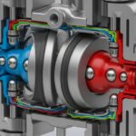
![Cutaway 3D render of an industrial air-operated double-diaphragm pump showing internal components.]()
Understanding Diaphragm Pumps: A Comprehensive Guide for Industrial Plants
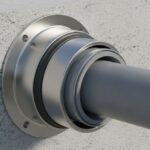
![A metallic pipe sleeve embedded in a concrete wall with a carrier pipe passing through it.]()
What is a Pipe Sleeve and How Does It Protect Piping?
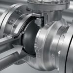
![Industrial stainless steel swing check valve installed in a pipeline with a flow direction arrow.]()
What are Check Valves? Types of Check Valves & Their Symbols
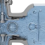
![Cross-section diagram of a control valve showing cavitation bubbles and flashing liquid.]()
How to Prevent Control Valve Cavitation and Flashing Damage
![Side-by-side comparison of ASME Section VIII Division 1 and Division 2 pressure vessels with technical blueprints.]()
Understanding the Difference Between ASME Sec VIII Div 1 vs Div 2