What is Steam Blowing and the Steam Blowing Procedure?
In my 20 plus years of commissioning utility-scale power plants and petrochemical complexes, I have seen many engineers underestimate the sheer destructive potential of a tiny piece of weld slag. When a steam turbine is spinning at 3,000 or 3,600 RPM, even a microscopic particle traveling at supersonic speed acts like a bullet. It will pit turbine blades, disrupt steam flow dynamics, and potentially cause catastrophic rotor imbalance.
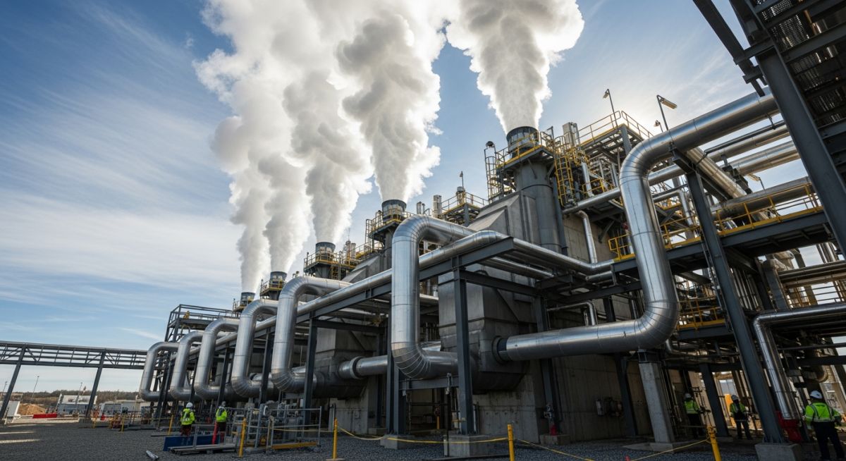
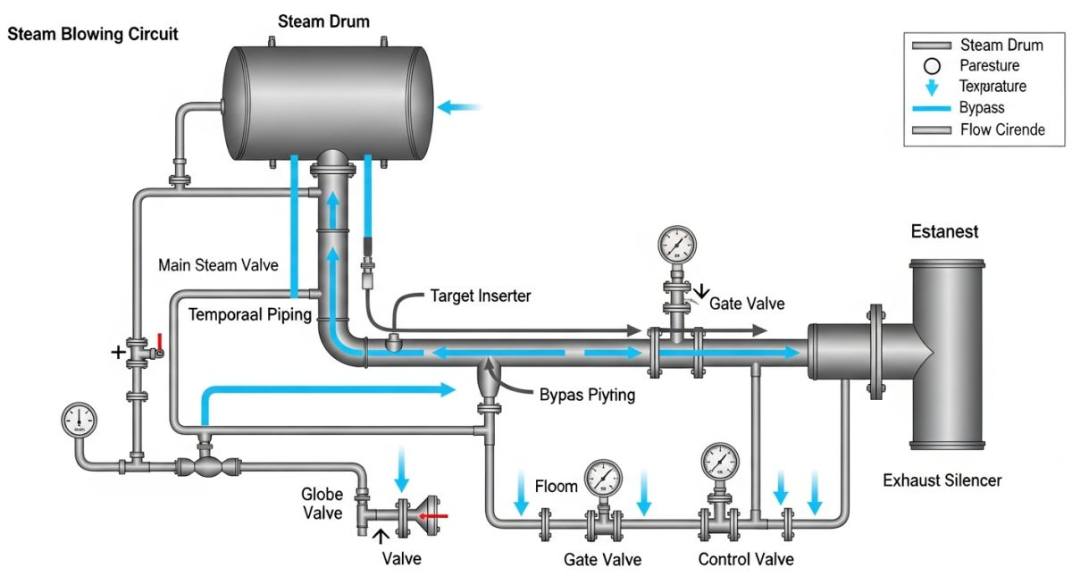
That is where the steam blowing procedure comes in. It is not a simple system flush; it is a highly engineered thermodynamic event. We temporarily redirect high-pressure steam through the newly installed piping and vent it to the atmosphere. By doing this, we subject the piping to kinetic forces and thermal shocks far exceeding anything it will experience during normal operation. This ensures that any debris that could possibly break loose in the future is dislodged and blown out safely beforehand.
Key Takeaways from This Guide:
- Understand the core physics behind the Disturbance Factor (DF) and why it must exceed 1.2.
- Compare the operational differences between continuous and discontinuous (puffing) blowing methods.
- Learn how to design temporary piping, target plates, and exhaust silencers to withstand massive reaction forces.
- Access a field-tested site verification checklist to ensure safe execution.
Why is the Steam Blowing Procedure Required?
Piping System Cleaning: The execution of a structured steam blowing procedure is required to eliminate internal contaminants that would otherwise impact turbine blades at supersonic speeds. This operational safety step is governed by ASME B31.1 power piping guidelines to guarantee system cleanliness before commercial operation.
To clean a pipe effectively, the steam we blow through it must exert a greater drag force on any internal debris than the steam during normal operation ever could. We quantify this using a dimensionless parameter called the Disturbance Factor (DF), also known as the Cleaning Force Ratio (CFR).
The mathematical formula for calculating the Disturbance Factor is:
Where:
mb = Mass flow rate of steam during the blowing process (expressed in kilograms per second)
vb = Specific volume of steam during the blowing process (expressed in cubic meters per kilogram)
mm = Maximum mass flow rate of steam during normal plant operation (expressed in kilograms per second)
vm = Specific volume of steam during normal plant operation (expressed in cubic meters per kilogram)
For a steam blow to be considered technically successful, the DF must be maintained between 1.2 and 1.7 throughout the target piping run. If the DF falls below 1.2, the cleaning run is ineffective because the kinetic energy is insufficient to dislodge adhered mill scale. If the DF exceeds 1.7, you risk overloading temporary piping supports and causing structural damage to the piping system.
In my experience, many field engineers fail to calculate the dynamic thrust forces acting on temporary piping during a blow. When high-pressure steam is vented to the atmosphere, the reaction force at the exhaust tip can easily exceed several tons. If your temporary anchors and structural guides are not designed to handle these transient loads, the piping will jump off its supports, leading to catastrophic structural failure and severe personnel hazard.
The Two Primary Steam Blowing Methodologies
Depending on the boiler capacity, piping volume, and water availability, we select one of two primary methods:
- Continuous Steam Blowing (Low Pressure): This method maintains a continuous, steady-state flow of steam through the system. The boiler is fired continuously, and steam is regulated through a temporary control valve. This method is highly efficient for large utility boilers with high water-makeup capacities, as it allows for rapid cleaning cycles.
- Discontinuous / Puffing Steam Blowing (Thermal Shock): Here, we bottle up steam pressure in the boiler and then open a fast-acting temporary valve to release a massive “puff” of steam. This creates a severe thermal shock. The rapid expansion and contraction of the piping breaks loose stubborn mill scale. This is the preferred method when boiler water makeup capacity is limited.
| Parameter | Continuous Steam Blowing | Discontinuous (Puffing) Blowing |
|---|---|---|
| Boiler Pressure Requirements | Low to Moderate (Steady State) | High (Accumulated in Drum) |
| Demineralized Water Consumption | Extremely High (Continuous Makeup) | Low to Moderate (Batch Makeup) |
| Thermal Shock Effectiveness | Moderate (Relies on Kinetic Energy) | Excellent (Rapid Temperature Cycles) |
| Temporary Piping Stress | Steady, Predictable Loads | High Transient Dynamic Thrusts |
| Typical Duration | Shorter overall calendar time | Longer (Requires thermal cool-down cycles) |
| Component / Entity | Standard Specification | Engineering Acceptance Criteria |
|---|---|---|
| Target Plate Material | Polished Soft Copper or Aluminum | Mirror finish, free of pre-existing scratches |
| Acceptance Criteria (ASME B31.1) | Turbine Manufacturer Guidelines | No impacts > 0.2mm; max 3 micro-impacts per square inch |
| Temporary Piping Class | ASME B31.3 / ASME B31.1 | Must match or exceed the design pressure of the blow |
| Exhaust Silencer Noise Limits | OSHA 1910.95 Compliance | Typically less than 115 dBA at the boundary limit |
How to Execute the Steam Blowing Procedure?
Pre-Commissioning Checklist: A rigorous field checklist ensures that all temporary piping, valves, and target plate inserters are verified before steam is introduced. This protocol aligns with ASME B31.1 and developer specifications to mitigate high-pressure hazards.
Before you crack open any steam valves, you must verify that the entire system is physically prepared to handle the thermal expansion and dynamic forces. Below is the exact checklist I use during pre-commissioning walks.
Pre-Steam Blow Field Verification Checklist
-
Temporary Piping Support Inspection: Verify that all temporary piping anchors, guides, and spring hangers are installed per the stress analysis report. Ensure no temporary piping loads are transferred to the turbine casing.
-
Thermal Expansion Clearance: Check that the temporary piping has adequate room to expand. A 100-meter run of carbon steel piping can expand by more than 250mm when heated to steam temperatures.
-
Target Plate Inserter Functionality: Test the manual or pneumatic target plate inserter mechanism. It must insert and retract smoothly without steam leakage.
-
Exhaust Area Exclusion Zone: Establish a physical barricade around the steam exhaust silencer. The exclusion zone must account for high-temperature steam plumes and extreme noise levels.
-
Drain and Trap Isolation: Ensure all permanent steam traps are isolated and temporary bypass drains are wide open to prevent condensate accumulation and water hammer.
Field Case Study: Real-World Application
During the commissioning of a 600MW combined-cycle power plant in Southeast Asia, the commissioning team completed 15 steam blows on the main steam line, but the target plates continued to show heavy pitting. The team was running out of demineralized water and faced severe project delays. Upon reviewing their calculations, I discovered they had sized the temporary piping too large (12-inch instead of 10-inch), which dropped the steam velocity. Their actual Disturbance Factor (DF) was only 0.85, meaning the steam was not moving fast enough to clean the pipe.
I immediately instructed the team to replace the temporary piping run with a smaller 10-inch line to restrict the flow area and increase velocity. We also adjusted the boiler drum pressure to optimize the specific volume of the steam. These changes successfully raised the Disturbance Factor to 1.45. Within just three subsequent steam blows, we achieved a mirror-finish target plate with zero micro-impacts, satisfying the steam turbine manufacturer’s strict warranty requirements.
My Professional Recommendation: Never guess your steam blowing parameters. Always perform a rigorous hydraulic simulation using software like PIPENET or HTRI to verify that your temporary piping configuration achieves the target Disturbance Factor at the lowest possible boiler pressure. This saves water, fuel, and schedule time.
FAQs on the Steam Blowing Procedure
Commissioning FAQs: This technical reference addresses common field queries regarding steam velocities, target plate materials, and safety protocols during steam blowing operations. These answers comply with standard industry practices and ASME guidelines.
What is the typical target plate material used in steam blowing?
Why is a Disturbance Factor (DF) of 1.2 to 1.7 required?
How do you prevent water hammer during the steam blowing procedure?
What is the role of a steam silencer during this process?
Can we use air blowing instead of steam blowing for steam lines?
How is the cleanliness of the steam line officially certified?
===
Complete Course on
Piping Engineering
Check Now
Key Features
- 125+ Hours Content
- 500+ Recorded Lectures
- 20+ Years Exp.
- Lifetime Access
Coverage
- Codes & Standards
- Layouts & Design
- Material Eng.
- Stress Analysis
