Table of Contents
What is a Valve Trim? Types, Components, and Selection
In my 20+ years of piping engineering, I have seen many young engineers mistake the valve body for the most critical part of a control valve. Let me tell you a hard truth: the body is just a pressure containment vessel. The real magic—and the real engineering headache—happens inside. The valve trim is the beating heart of any control valve. If you select the wrong trim, you will face cavitation, flashing, severe erosion, and premature failure within weeks of commissioning. I remember a project in a high-pressure gas plant where a minor oversight in trim selection led to a complete plant shutdown. That is why understanding trim components, types, and selection charts is not optional; it is a core survival skill for any piping professional.
Key Engineering Takeaways
- Trim components dictate the flow control characteristics (linear, equal percentage, quick opening).
- Material selection must comply with NACE MR0175/ISO 15156 for sour service.
- Anti-cavitation and noise-attenuation trims are mandatory for high pressure drop applications.
How to Select the Right Valve Trim for Process Control
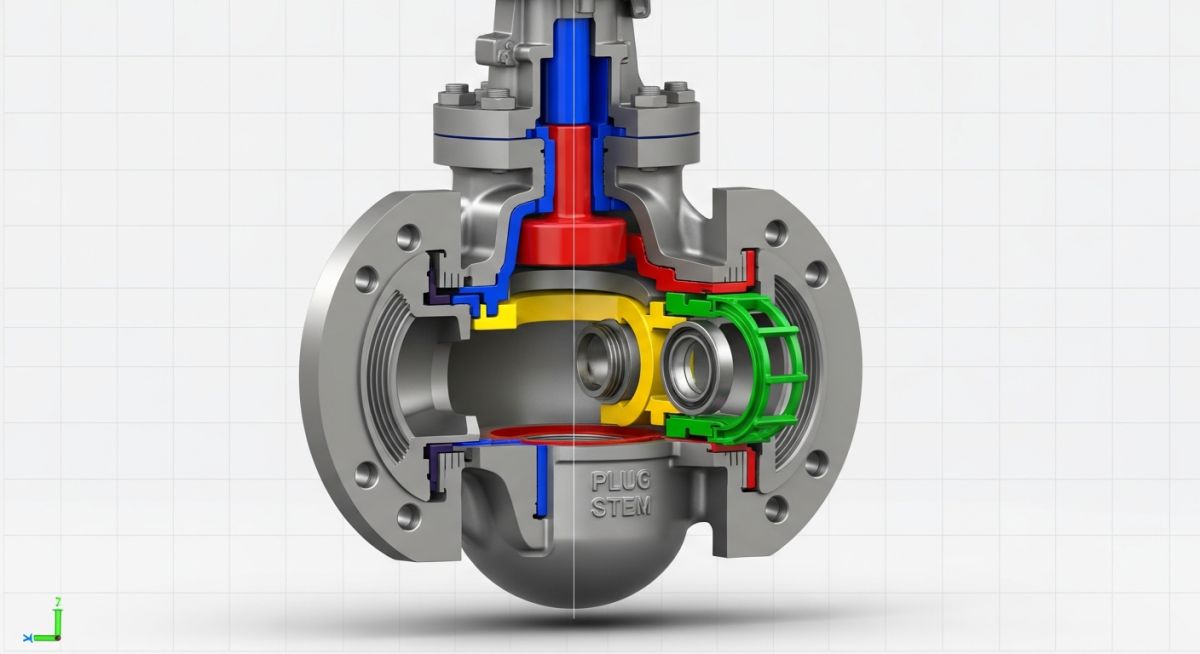
To design an efficient piping system, you must understand the individual components that make up the valve trim. These typically include the valve stem, the plug, the seat ring, the cage, and the guiding bushings. Each of these parts plays a distinct role in managing fluid dynamics. The stem transmits the actuator’s linear or rotary force to the plug. The plug acts as the primary throttling element, modulating the flow area against the seat ring. The cage provides structural support, guides the plug, and can even house specialized flow-passages to reduce noise and cavitation.
Flow Characteristics and Mathematical Modeling
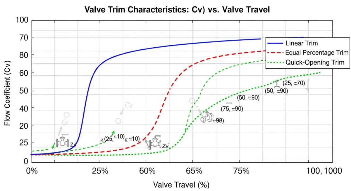
The relationship between valve lift and flow rate is defined by the trim’s inherent flow characteristic. In my field experience, selecting the wrong characteristic leads to control loop instability. The three primary profiles are:
- Linear Trim: Flow rate is directly proportional to valve travel. Used when the pressure drop across the valve remains relatively constant.
- Equal Percentage Trim: Equal increments of valve travel produce equal percentage changes in the existing flow. This is the most common choice for process control where pressure drop varies.
- Quick Opening Trim: Provides maximum flow capacity at minimum travel. Typically reserved for on-off service or emergency shutdown systems.
To calculate the required flow coefficient (Cv) for liquid service, we use the standard ISA formula:
Cv = Q * square root ( G / dP )
Where Q is the flow rate in gallons per minute, G is the specific gravity of the fluid, and dP is the pressure drop across the valve in psi.
Mitigating Cavitation and Flashing
When the local pressure of a liquid drops below its vapor pressure, vapor bubbles form. If the pressure recovers above the vapor pressure, these bubbles collapse violently—a phenomenon known as cavitation. To prevent this, we utilize multi-stage or labyrinth-path trims. These designs force the fluid through a series of restrictive, tortuous paths, reducing the pressure gradually without allowing the local pressure to dip below the vapor pressure.
Standard API 600 Valve Trim Chart and Materials
Selecting the correct trim material is a balancing act between corrosion resistance, erosion resistance, temperature limits, and cost. The table below outlines the standard API trim numbers commonly specified in industrial piping projects.
| Trim No. | Typical Material | Hardness (HB) | Temperature Range | Common Applications |
|---|---|---|---|---|
| Trim 1 | 13% Chromium (13Cr) | Min 250 | -29 to 593 °C | Mild corrosive, steam, oil, and gas services. |
| Trim 5 | Stellite (Hardfaced) | Min 350 | -268 to 650 °C | High pressure, severe erosive, and steam services. |
| Trim 8 | 13Cr and Stellite | Min 250 / 350 | -29 to 593 °C | Universal standard for refinery gate valves. |
| Trim 10 | 316 Stainless Steel | Non-hardened | -268 to 425 °C | Corrosive chemical and cryogenic services. |
| Trim 12 | 316 SS and Stellite | Min 350 (Seat) | -268 to 650 °C | Sour gas, corrosive chemicals with high pressure. |
| Trim 16 | Monel | Non-hardened | -196 to 450 °C | Hydrofluoric acid and marine environments. |
This matrix maps the relationship between valve trim configurations, design standards, and operational limits. Use this as a quick reference during the front-end engineering design (FEED) phase.
| Trim Configuration | Guiding Type | Max Pressure Drop | Leakage Class (FCI 70-2) | Applicable Standards |
|---|---|---|---|---|
| Contoured Plug | Post / Stem Guided | Low to Medium (< 20 bar) | Class IV or V | ASME B16.34 |
| Standard Cage | Cage Guided | Medium (< 50 bar) | Class IV, V, or VI | ISA 75.01 |
| Multi-Stage Labyrinth | Cage Guided | High (> 100 bar) | Class V | API 6D / ASME B16.34 |
Field Inspection Checklist for Valve Trim Installation
When you are at the construction site, you cannot rely solely on paperwork. You must physically verify the valve trim before it is welded or bolted into the piping run. Here is the checklist I have developed over years of field inspections to prevent costly re-work.
Pre-Installation Verification Steps
-
Verify the API trim number stamped on the valve nameplate matches the piping specification and data sheet. -
Inspect the plug and seat ring for any scratches, pitting, or machining defects before installation. -
Perform a manual stroke check to ensure the stem moves smoothly without binding or excessive friction. -
Confirm that the flow direction arrow on the valve body aligns with the actual process flow direction. -
Check the packing material (PTFE or Graphite) to ensure it is rated for the design temperature of the system. -
Verify that the seat tightness test certificate complies with API 598 leakage standards.
Field Case Study: Real-World Application
Recommendation: Always perform a comprehensive sizing and noise calculation using ISA 75.01 standards before finalizing the trim selection for any gas letdown service with a pressure ratio greater than 2:1.
Frequently Asked Engineering Questions
What is the difference between valve trim and valve internals?
How does the API 600 trim chart help in material selection?
What is the purpose of a hard-faced (Stellite) valve trim?
How do you identify cavitation damage on a valve plug?
When should I select an equal percentage flow characteristic?
Can you mix different trim materials in a single valve?
===FAQ_BLOCK===
Complete Course on
Piping Engineering
Check Now
Key Features
- 125+ Hours Content
- 500+ Recorded Lectures
- 20+ Years Exp.
- Lifetime Access
Coverage
- Codes & Standards
- Layouts & Design
- Material Eng.
- Stress Analysis

📚 Recommended Resources: valve trim
Read these Guides
🎓 Advanced Training


Related posts:
![A mechanical sucker rod pumpjack operating in an oil field at sunset]()
What is Sucker Rod Pump System in Oil Production?
![Piping material engineer reviewing technical specifications on a tablet in an industrial plant.]()
How a Piping Material Engineer Drives Industrial Project Success
![Industrial refinery plant showing various types of static equipment]()
What is Static Equipment? Types and List of Static Equipments
![Side-by-side comparison of industrial process piping and power plant steam piping systems.]()
Differences Between ASME B31.3 and B31.1: B31.3 vs B31.1
![Large industrial steel storage tank under construction with cranes and scaffolding]()
Storage Tank Construction Method Statement: Step-by-Step Engineering Guide
![Towering steel cold box structure at an industrial cryogenic air separation unit.]()
What is a Cold Box in Cryogenic Plant Systems?