Table of Contents

What is a Boom Lift? Applications, Sizes, and Types
In my 20 years of managing heavy industrial piping and construction projects, I have seen how the selection of aerial work platforms directly impacts project timelines and site safety. When you are dealing with high-elevation pipe racks, complex structural steel installations, or overhead electrical systems, a standard ladder or scaffold simply will not cut it. That is where the hydraulic power of a modern boom lift becomes indispensable.
These machines are engineered to solve the dual challenge of height and outreach. Unlike scissor lifts, which only move vertically, these units can extend outward at various angles, allowing operators to navigate over obstacles, piping loops, and structural barriers. Understanding the mechanical limits, load capacities, and structural configurations of these machines is a core requirement for any field engineer or construction manager.
Key Engineering Takeaways:
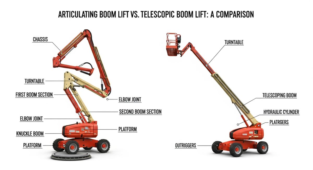
- Reach Versatility: Articulating models offer “up-and-over” clearance, while telescopic models maximize straight-line horizontal and vertical reach.
- Regulatory Compliance: All operations must strictly align with OSHA 1926.453 and ANSI A92 design and safety standards.
- Load Limitations: Exceeding the rated platform capacity (typically 500 to 1,000 pounds) alters the machine’s center of gravity, risking catastrophic tip-over.
What Are the Primary Boom Lift Classifications?
Aerial Lift Classifications: Boom lift selection depends on the kinematic requirements of the workspace, categorized primarily into articulating and telescopic configurations governed by ANSI A92.20 design standards. Choosing the correct configuration ensures structural stability, safe working load compliance, and optimal reach efficiency.
When designing a construction sequence or planning maintenance around live process piping, you must evaluate the physical envelope of the machine. The two primary families of self-propelled aerial platforms are articulating (knuckle) booms and telescopic (stick) booms. Each operates on distinct mechanical principles.
1. Articulating Boom Lifts
Articulating models feature multiple boom sections that fold or “bend” via hydraulic knuckle joints. This design provides incredible versatility for indoor and congested outdoor environments. In my experience, these are the go-to machines when you need to route a platform over a live pipe rack or around structural columns. The primary advantage is the “up-and-over” capability, allowing the operator to reach a target area without positioning the base directly beneath it.
2. Telescopic Boom Lifts
Telescopic models utilize a straight, extendable arm that slides out hydraulically. These machines are engineered for maximum horizontal outreach and extreme heights. If your project requires working on high-rise facades, exterior industrial vessels, or open-span bridge structures, a telescopic unit is the correct choice. They offer superior stability at maximum extension but require a larger clear operating footprint because they lack the ability to bend around obstacles.
Never underestimate the impact of wind shear on an extended boom. The lateral force exerted by wind on the platform, operator, and boom structure increases the overturning moment exponentially at high extensions.
Always monitor local wind speeds using a calibrated anemometer. Most manufacturers mandate immediate shutdown and boom retraction when wind speeds exceed 28 mph (12.5 m/s).
Engineering Calculations: Stability and Load Limits
The structural stability of an aerial platform is governed by the relationship between the machine’s tipping line and its combined center of gravity. Let us look at how wind force and platform load contribute to the overturning moment.
Wind Force Calculation (Plain Text Formula):
Wind_Force (F_w) = 0.5 * air_density * wind_speed^2 * drag_coefficient * projected_area
Where:
- air_density = 1.225 kg/m^3 (standard sea-level air density)
- wind_speed = 12.5 m/s (maximum allowable operating wind speed under OSHA guidelines)
- drag_coefficient = 1.2 (typical drag coefficient for a person on an open platform)
- projected_area = 1.4 m^2 (combined projected surface area of operator and platform basket)
Example Calculation:
F_w = 0.5 * 1.225 * (12.5)^2 * 1.2 * 1.4 = 160.78 Newtons
Overturning Moment (M_o) at Base:
M_o = (Platform_Load * Horizontal_Reach) + (Wind_Force * Platform_Height)
If Platform_Load = 2227 Newtons (227 kg / 500 lbs), Horizontal_Reach = 15 meters, and Platform_Height = 20 meters:
M_o = (2227 * 15) + (160.78 * 20) = 33405 + 3215.6 = 36620.6 Newton-meters
This calculated overturning moment must always remain well below the machine’s stabilizing moment (the weight of the chassis and counterweight multiplied by the distance to the tipping line). Modern machines utilize load-sensing systems that automatically cut off boom extension if the safe operating envelope is breached.
Selecting the correct machine size is a balance between reach requirements, site access constraints, and ground bearing capacity. The table below outlines the standard size classes found across major industrial rental fleets.
| Size Class | Platform Height | Horizontal Reach | Unrestricted Capacity | Gross Weight |
|---|---|---|---|---|
| Compact / Electric | 30 ft – 45 ft (9.1 m – 13.7 m) | 20 ft – 25 ft (6.1 m – 7.6 m) | 500 lbs (227 kg) | 12,000 – 16,000 lbs |
| Mid-Size Diesel | 60 ft – 85 ft (18.3 m – 25.9 m) | 50 ft – 75 ft (15.2 m – 22.8 m) | 500 – 1,000 lbs (227 – 454 kg) | 22,000 – 38,000 lbs |
| Ultra-Reach | 120 ft – 185 ft (36.6 m – 56.4 m) | 75 ft – 90 ft (22.8 m – 27.4 m) | 500 – 1,000 lbs (227 – 454 kg) | 45,000 – 60,000 lbs |
This matrix maps specific equipment types to their core mechanical components, structural acronyms, physical parameters, and governing standards.
| Equipment Type | Core Mechanical Entity | Structural Acronym | Physical Parameter | Governing Standard |
|---|---|---|---|---|
| Articulating Boom | Dual-Riser Knuckle Joint | AWP-A (Articulating) | Up-and-Over Clearance | ANSI A92.20 |
| Telescopic Boom | Multi-Stage Hydraulic Cylinder | AWP-T (Telescopic) | Maximum Horizontal Outreach | ANSI A92.20 |
| Crawler Mounted | Continuous Rubber Tracks | AWP-C (Crawler) | Low Ground Bearing Pressure | OSHA 1926.453 |
How to Perform a Boom Lift Inspection
Pre-Operation Inspection Protocols: Daily pre-start inspections of aerial work platforms are mandatory under OSHA 1926.453 and ANSI A92.22 guidelines to identify mechanical, hydraulic, and structural defects before operation. This systematic verification process mitigates the risk of catastrophic structural failure or tip-over events during high-elevation tasks.
Before any operator steps into the platform basket, a comprehensive walk-around inspection must be completed and documented. In my years on site, I have found that a structured checklist is the best defense against mechanical failures.
Daily Pre-Start Inspection Checklist:
-
Hydraulic System Integrity: Check all cylinders, hoses, and fittings for leaks. Verify hydraulic fluid levels are within the manufacturer’s specified operating range.
-
Structural Welds and Pins: Inspect critical structural welds along the boom sections, turntable, and platform support frame for cracks, deformation, or corrosion. Ensure all pivot pins are secured with retaining clips.
-
Emergency Controls and Safety Devices: Test the ground-level emergency lowering system, platform tilt alarms, and the automatic limit switches that prevent operation on unsafe slopes.
-
Tires and Ground Contact: For wheeled units, check tire pressure and inspect for deep cuts or embedded debris. For crawler units, verify track tension and link wear.
-
Personal Protective Equipment (PPE): Confirm that the operator’s full-body harness and energy-absorbing lanyard are inspected, rated, and securely attached to the designated platform anchor point.
Field Case Study: Real-World Application
The Challenge: High-Elevation Piping Installation
During a major expansion at a petrochemical refinery in Texas, our team had to install a series of 24-inch overhead bypass piping headers. The installation path crossed directly over an active, low-clearance utility rack.
The target height was 65 feet, but the ground directly beneath the installation point was congested with concrete foundations, electrical conduits, and soft, uncompacted soil. A standard scissor lift could not access the area, and a crane lift was deemed too high-risk due to the proximity of live high-voltage lines.
The Engineering Solution
I specified an 85-foot articulating boom lift equipped with continuous rubber tracks (crawler chassis) and a secondary guarding system. The articulating knuckle allowed us to position the machine’s base 35 feet away on stable, compacted ground, extending the boom “up-and-over” the low-clearance utility rack to reach the exact installation coordinates.
The crawler tracks distributed the machine’s 36,000-pound gross weight over a wider surface area, reducing ground bearing pressure to less than 8 psi. This eliminated the risk of ground subsidence near the concrete foundations.
My Recommendation: When dealing with complex, congested industrial environments, always perform a detailed 3D reach study before selecting your machine. Articulating models with track drives are highly effective for navigating tight spaces and soft ground, saving significant time compared to building temporary scaffolding.
Frequently Asked Engineering Questions
What is the primary difference between a boom lift and a scissor lift?
Can a boom lift be operated on sloped or uneven ground?
What are the wind speed limits for operating a boom lift safely?
How often do boom lifts require structural and mechanical inspections?
What is the difference between an articulating and a telescopic boom lift?
What safety harness requirements apply to boom lift operators?
===FAQ_BLOCK===
Complete Course on
Piping Engineering
Check Now
Key Features
- 125+ Hours Content
- 500+ Recorded Lectures
- 20+ Years Exp.
- Lifetime Access
Coverage
- Codes & Standards
- Layouts & Design
- Material Eng.
- Stress Analysis

📚 Recommended Resources: boom lift
Read these Guides
Related posts:
![A mechanical sucker rod pumpjack operating in an oil field at sunset]()
What is Sucker Rod Pump System in Oil Production?
![Piping material engineer reviewing technical specifications on a tablet in an industrial plant.]()
How a Piping Material Engineer Drives Industrial Project Success
![Industrial refinery plant showing various types of static equipment]()
What is Static Equipment? Types and List of Static Equipments
![Side-by-side comparison of industrial process piping and power plant steam piping systems.]()
Differences Between ASME B31.3 and B31.1: B31.3 vs B31.1
![Large industrial steel storage tank under construction with cranes and scaffolding]()
Storage Tank Construction Method Statement: Step-by-Step Engineering Guide
![Cutaway diagram of a globe control valve highlighting the internal valve trim components]()
What is a Valve Trim? Types, Components, and Selection


