Table of Contents
What is a Turnbuckle and How to Install It?
In my 20 years of managing heavy industrial piping and structural rigging projects, I have seen minor hardware oversights lead to catastrophic structural failures. The humble turnbuckle is often treated as a simple commodity, yet it is the primary mechanism holding massive pipe bridges, structural bracing, and guy-wire systems in perfect equilibrium. Understanding how to select, calculate, and install these devices is not just a basic skill; it is a core requirement for structural integrity.
Key Engineering Takeaways
- Learn the exact mechanical principles behind left-hand and right-hand threaded bodies.
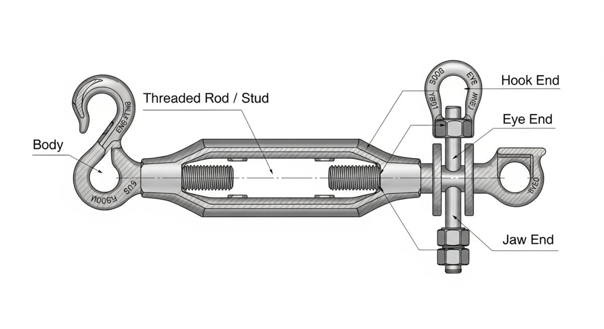
- Identify the structural differences between eye, hook, and jaw end fittings.
- Calculate safe working loads using ASME B30.26 design margins.
- Execute a flawless installation sequence to prevent thread galling.
- Master the inspection criteria to identify fatigue before failure occurs.
Complete Course on
Piping Engineering
Check Now
Key Features
- 125+ Hours Content
- 500+ Recorded Lectures
- 20+ Years Exp.
- Lifetime Access
Coverage
- Codes & Standards
- Layouts & Design
- Material Eng.
- Stress Analysis
How Does a Turnbuckle Manage Structural Tension?
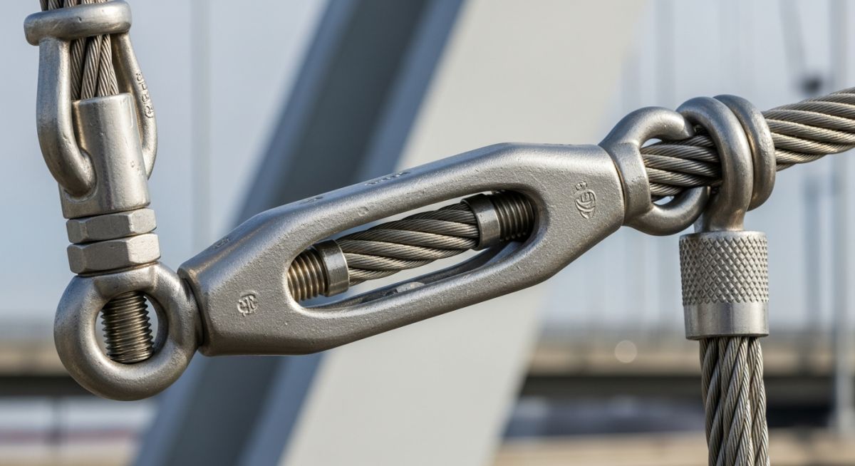
The core mechanics of a turnbuckle rely on a central metal frame (the body) with internal threads at each end. One end is tapped with a right-hand (RH) thread, while the opposite end is tapped with a left-hand (LH) thread. When you rotate the body, both end fittings are either drawn inward to increase tension or pushed outward to release tension, without rotating the attached cables or rods. This elegant design prevents the twisting and potential untwisting of wire ropes during adjustment.
Engineering Calculations for Safe Working Load (SWL)
When designing structural bracing, we must calculate the tensile stress area of the threaded end fittings. The tensile stress area (As) for standard unified inch threads is calculated using the following formula:
Where:
D = Nominal diameter of the thread (inches)
n = Number of threads per inch (TPI)
To determine the Safe Working Load (SWL) under ASME B30.26, a design factor of 5:1 is applied to the ultimate tensile strength of the material. For structural tie rods, the allowable tensile stress is governed by the American Institute of Steel Construction (AISC) specifications, which typically limit the stress to 0.60 times the yield strength (Fy) of the material.
Material Selection Criteria
In my experience, selecting the correct material is just as important as the load calculation. For offshore and chemical processing environments, Grade 316 stainless steel is the standard due to its superior resistance to chloride-induced pitting. For heavy industrial rigging and construction, hot-dip galvanized carbon steel compliant with ASTM F1145 is preferred because it offers high yield strength and excellent atmospheric corrosion protection at a lower cost.
The table below outlines the standard dimensions, take-up capacities, and Safe Working Loads (SWL) for hot-dip galvanized steel turnbuckles in accordance with ASTM F1145. These values assume a standard 5:1 safety factor.
| Thread Diameter (in) | Take-Up Range (in) | Safe Working Load (lbs) | Ultimate Strength (lbs) |
|---|---|---|---|
| 3/8 | 6 | 1,200 | 6,000 |
| 1/2 | 6, 9, 12 | 2,200 | 11,000 |
| 5/8 | 6, 9, 12, 18 | 3,500 | 17,500 |
| 3/4 | 6, 9, 12, 18, 24 | 5,200 | 26,000 |
| 1.0 | 12, 18, 24, 36 | 10,000 | 50,000 |
Different end fittings serve distinct structural purposes. This matrix maps the common configurations, their mechanical limitations, and the primary design standards governing their application.
| Fitting Combination | Primary Application | Mechanical Limitation | Governing Standard |
|---|---|---|---|
| Jaw & Jaw | Structural bracing, high-vibration connections | Requires matching connection plates (gussests) | ASME B30.26 |
| Eye & Eye | Straight-line wire rope tensioning, guy wires | Requires shackles for connection to closed loops | ASTM F1145 |
| Hook & Hook | Temporary rigging, quick-release setups | Reduced load capacity; prone to slipping under slack | ASME B30.26 |
| Jaw & Eye | Transitioning between structural plates and cables | Asymmetric loading must be carefully aligned | ASTM F1145 |
What is the Turnbuckle Installation Verification Protocol?
Before any tensioning system is put into service, field engineers must verify that the hardware has been installed correctly. Skipping these steps can lead to thread stripping, structural misalignment, or sudden failure under dynamic wind loads.
Field Verification Checkpoints
-
Verify Thread Lubrication: Apply a high-quality anti-seize compound to stainless steel threads to prevent galling during tensioning.
-
Check Minimum Thread Engagement: Ensure the thread length inside the body is at least 1.5 times the nominal thread diameter. Never back the threads out past the inspection hole if one is present.
-
Inspect Alignment: Confirm the turnbuckle is aligned in a direct straight line with the pull vector. Any angular offset introduces bending moments that drastically reduce load capacity.
-
Confirm Locking Mechanism: Install locknuts (jam nuts) or wire wraps to prevent rotation under vibration. For structural applications, lockwires are preferred over jam nuts as they do not introduce additional tensile stress.
-
Inspect for Physical Defects: Check for cracks, thread deformation, or bending in the body or end fittings. Reject any hardware showing signs of field modification or welding.
Field Case Study: Real-World Application
The Problem: Structural Instability in Coastal Pipe Racks
During a structural audit of a coastal pipe rack support system, I discovered several 1.5-inch turnbuckles showing severe thread corrosion and minor bending. The original contractor had installed hook-and-hook turnbuckles instead of jaw-and-jaw configurations, and failed to apply locknuts. High winds caused cyclic vibration, backing out the threads and reducing thread engagement to less than 0.5 inches, putting the entire pipe rack at risk of collapse.
The Outcome: Remediation and Stabilization
We immediately engineered a temporary shoring system, replaced the compromised hardware with hot-dip galvanized jaw-and-jaw turnbuckles compliant with ASTM F1145, applied heavy-duty anti-seize, and secured them with locknuts. The structural alignment was restored, and subsequent vibration testing showed zero thread backing, securing the pipe rack for its 25-year design life.
This case highlights why proper hardware selection is not optional. Hook-type fittings should never be used in permanent structural applications where vibration or wind loading is expected.
Frequently Asked Engineering Questions
What is the difference between a turnbuckle and a tension sleeve?
How do you prevent thread galling in stainless steel turnbuckles?
Can turnbuckles be used for overhead lifting applications?
What is the purpose of a locknut (jam nut) on a turnbuckle?
How do you calculate the required take-up length?
What are the inspection rejection criteria for rigging turnbuckles?
===

Related posts:
![Industrial worker welding a large structural steel I-beam in a fabrication facility.]()
What is Structural Steel Fabrication and How Does It Work?
![Stack of newly manufactured galvanized steel pipes in an industrial warehouse]()
Understanding the Galvanized Pipe Meaning in Modern Piping Systems
![Industrial Alloy 625 piping components in a manufacturing plant]()
What is Alloy 625? Properties, Grades, and Applications of Alloy 625
![Close-up of a fractured steel shaft showing metal fatigue beach marks and failure zones.]()
What is Metal Fatigue and How Do Engineers Prevent It?
![Industrial machinery fitted with smart sensors displaying real-time condition-based maintenance data on a digital overlay.]()
What is Condition-Based Maintenance and How Does It Work?
![Comparison of high viscosity honey and low viscosity water pouring to demonstrate fluid resistance]()
Understanding Newton's Law of Viscosity and Key Fluid Flow Factors