Table of Contents
What is a Slug Catcher? Types, Working, and Design Steps
In my 20+ years of piping engineering, I have seen many facilities brought to their knees by a single massive liquid slug. Imagine a high-velocity gas stream carrying a wall of liquid hydrocarbons and water, slamming directly into a compressor station or a gas sweetening unit. The result is catastrophic: blown compressor valves, flooded amine towers, and weeks of unplanned downtime. That is where the slug catcher comes in. It is the first line of defense in any multiphase gas processing facility, acting as a giant shock absorber that tames the wild, unpredictable nature of multiphase pipeline flow.
Key Engineering Takeaways
- Understand the physical mechanisms behind hydrodynamic and pigging-induced liquid slugs.
- Master the structural and process differences between vessel-type and finger-type slug catchers.
- Learn the exact design steps required to size these systems under ASME B31.8 and ASME Section VIII.
- Identify the critical selection criteria based on operating pressure, liquid volume, and plot space.
Why Use a Slug Catcher in Pipelines?
Multiphase pipelines carry a mixture of natural gas, condensate, water, and sometimes corrosion inhibitors. Because gas travels much faster than liquid, the liquid tends to accumulate in the low points of the pipeline topography. Over time, this liquid accumulation is swept up by the high-velocity gas, forming a dense, fast-moving plug known as a “slug.”
Slugs are generated primarily through three mechanisms:
- Terrain-Induced Slugging: Occurs when liquid pools in pipeline valleys until the pressure build-up behind it pushes the entire liquid mass up the hill in one large wave.
- Hydrodynamic Slugging: Waves form on the gas-liquid interface inside the pipe. When these waves grow large enough to bridge the pipe cross-section, they form a slug.
- Pigging Slugs: When a pipeline inspection gauge (pig) is run through the line to clean it, it sweeps all accumulated liquid ahead of it, creating an enormous, predictable liquid slug at the terminal.
In my field audits, I have observed finger-type slug catchers vibrating violently during pigging runs. If the structural supports and anchor bolts are not designed for the dynamic momentum transfer of the incoming liquid slug, fatigue failure of the piping manifold will occur. Always perform a dynamic stress analysis using software like CAESAR II for the inlet piping.
The Physics of Separation
To separate the gas and liquid phases, we rely on gravity settling and momentum reduction. When the multiphase mixture enters the slug catcher, the flow area expands dramatically. This velocity drop reduces the kinetic energy of the fluid, allowing gravity to pull the heavier liquid droplets down while the lighter gas rises.
The terminal settling velocity of a liquid droplet in a gas stream is calculated using the drag coefficient and Stokes’ Law principles:
Where:
Vt = Terminal settling velocity of the liquid droplet (m/s)
g = Acceleration due to gravity (9.81 m/s²)
dp = Droplet diameter (meters, typically targeted at 100 to 150 microns for primary separation)
rho_l = Density of the liquid phase (kg/m³)
rho_g = Density of the gas phase (kg/m³)
Cd = Dimensionless drag coefficient of the droplet (dependent on the Reynolds number)
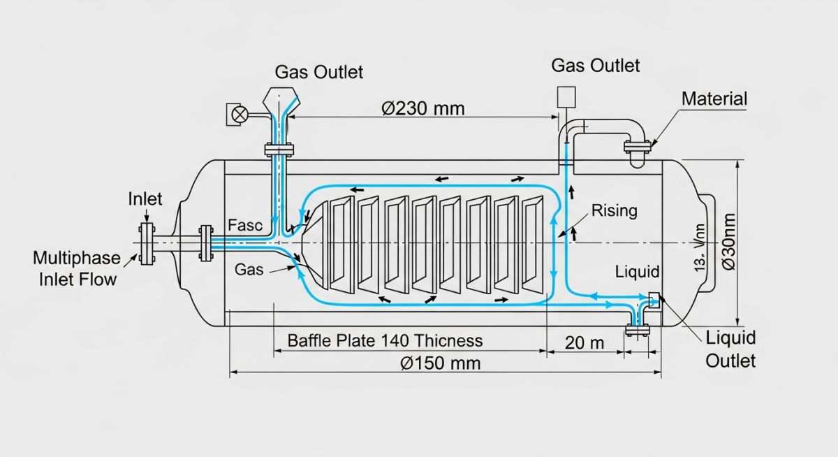
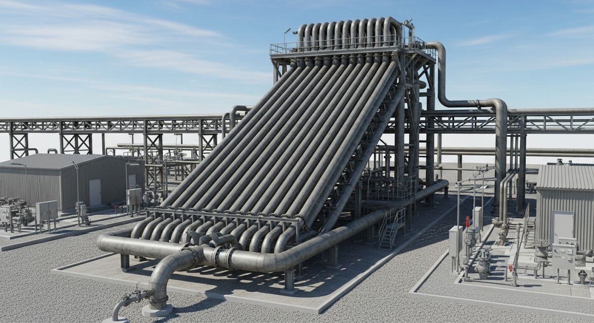
Vessel Type vs. Finger Type Configurations
There are two primary configurations used in industrial gas plants:
- Vessel Type: A large, conventional pressure vessel (either horizontal or vertical) designed according to ASME Section VIII. It is simple to design and has a small footprint, but becomes extremely expensive and heavy when high pressures and large storage volumes are required.
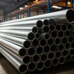
- Finger Type: A manifold of long, parallel, slightly sloped pipes (fingers) designed using piping codes like ASME B31.8 or ASME B31.3. The fingers act as storage tubes. This design is highly scalable and cost-effective for high-pressure applications because standard, high-strength line pipe can be used instead of thick-walled custom pressure vessels.
How to Select a Slug Catcher Type?
Selecting the correct configuration is a balance between capital expenditure, plot space, and operating pressure. In my experience, when design pressures exceed 70 barg and required liquid storage volumes exceed 500 barrels, finger-type designs almost always win on cost.
| Design Parameter | Vessel Type Slug Catcher | Finger Type Slug Catcher |
|---|---|---|
| Design Code | ASME Section VIII Div 1 / 2 | ASME B31.8 / ASME B31.3 |
| Pressure Range | Low to Moderate (< 50 barg preferred) | High to Very High (> 70 barg up to 150+ barg) |
| Liquid Storage Capacity | Limited (typically < 1,000 barrels) | Virtually unlimited (modular fingers) |
| Plot Space Footprint | Small, compact vertical/horizontal footprint | Very large (requires extensive land area) |
| Fabrication Location | Shop fabricated, shipped as complete unit | Field fabricated or modular skid assembly |
| Inspection & Maintenance | Easy internal access via manways | Difficult; requires pigging or specialized UT |
Technical Mapping & Specifications Matrix
To assist in your engineering design reviews, I have compiled a technical mapping matrix that links operational parameters to their corresponding design standards and physical limits.
| Entity / Parameter | Standard Reference | Typical Design Limit | Engineering Significance |
|---|---|---|---|
| Gas Velocity Limit | API RP 14E | F-factor < 0.35 to 0.50 m/s | Prevents liquid droplet re-entrainment in gas |
| Liquid Retention Time | API Spec 12J | 2 to 5 minutes | Allows dissolved gas bubbles to escape liquid |
| Slope of Fingers | Industry Best Practice | 1:100 to 1:200 (downward) | Ensures gravity drainage of liquid to low-point |
| Corrosion Allowance | ASME B31.8 / VIII | 3.0 mm to 6.0 mm | Accounts for wet CO2/H2S corrosive environments |
Design Steps for a Slug Catcher System
Designing a slug catcher is an iterative process that bridges transient multiphase flow simulation (using software like OLGA) with structural piping design. Below is the step-by-step methodology I follow on projects:
- Determine the Design Slug Volume: Run transient simulations for the worst-case pigging scenario at end-of-life flow rates. This gives you the maximum liquid volume that will arrive at the terminal.
- Size the Gas Separation Zone: Calculate the cross-sectional area required to keep the gas velocity below the critical droplet entrainment velocity using API RP 14E guidelines.
- Size the Liquid Storage Zone: For finger-type designs, calculate the number and length of fingers required to hold the design slug volume while maintaining a liquid seal at the outlet.
- Perform Structural Dynamic Analysis: Calculate the momentum force of the incoming slug. Apply this force as a dynamic load in your piping stress analysis to design the anchor blocks and supports.
Site Verification & Design Review Checklist
Before finalizing your slug catcher design package, verify that the following items have been addressed by your engineering team:
-
Transient Simulation Validation: Has the design slug volume been validated using a transient multiphase simulator (e.g., OLGA) for both pigging and ramp-up cases? -
Dynamic Load Factor (DLF): Has a DLF of 2.0 been applied to the structural support design to account for the sudden impact of the liquid slug front? -
Slope Verification: Are the fingers sloped downward at a minimum of 1:150 toward the liquid header to prevent liquid stagnation and sand accumulation? -
Sand Clean-out Facilities: Are high-pressure sand jetting connections and low-point drains included to clean out accumulated pipeline solids? -
Overpressure Protection: Are the pressure safety valves (PSVs) sized for the gas-blocked outlet case and thermal expansion of blocked-in liquid?
Field Case Study: Real-World Application
An onshore gas terminal in North Africa was receiving gas from a 36-inch offshore pipeline. During routine pigging operations, the existing horizontal vessel-type slug catcher was overwhelmed. The liquid level rose faster than the control valves could dump the liquid to storage. This resulted in massive liquid carryover into the downstream amine sweetening unit, causing severe amine foaming, loss of gas sweetening capacity, and an immediate emergency shutdown (ESD) of the entire facility. The plant was losing over 1.2 million per day of production.
I was brought in to lead the fast-track engineering remediation. We bypassed the inadequate vessel and designed a modular, 8-finger slug catcher using 48-inch API 5L X65 line pipe (1.25-inch wall thickness) designed under ASME B31.8. The fingers were 120 meters long, providing a dedicated liquid storage volume of 3,500 barrels. We incorporated a high-integrity pressure protection system (HIPPS) and automated liquid level control valves tied to the plant’s DCS.
The Outcome
The new finger-type system successfully handled its first pigging run six months later, capturing a 2,800-barrel liquid slug without a single drop of liquid carryover downstream. The sloped finger design allowed the liquid to drain smoothly to the low-point liquid header, where it was pumped to the condensate stabilization unit at a controlled rate of 500 barrels per hour. The plant has operated continuously without a single slug-related shutdown since the retrofit.
Frequently Asked Engineering Questions
1. What is the typical slope for a finger-type slug catcher?
2. How do you prevent gas blowby in a slug catcher?
3. Why are finger-type slug catchers designed under piping codes instead of vessel codes?
4. How do you handle sand and solids accumulation?
5. What is the function of the gas equalization header?
6. Can a slug catcher be used for three-phase separation?
===FAQ_BLOCK===
Complete Course on
Piping Engineering
Check Now
Key Features
- 125+ Hours Content
- 500+ Recorded Lectures
- 20+ Years Exp.
- Lifetime Access
Coverage
- Codes & Standards
- Layouts & Design
- Material Eng.
- Stress Analysis

📚 Recommended Resources: slug catcher
🎥 Watch Tutorials

Related posts:
![Industrial worker welding a large structural steel I-beam in a fabrication facility.]()
What is Structural Steel Fabrication and How Does It Work?
![A heavy-duty stainless steel turnbuckle tensioning a structural cable.]()
What is a Turnbuckle and How to Install It?
![Stack of newly manufactured galvanized steel pipes in an industrial warehouse]()
Understanding the Galvanized Pipe Meaning in Modern Piping Systems
![Industrial Alloy 625 piping components in a manufacturing plant]()
What is Alloy 625? Properties, Grades, and Applications of Alloy 625
![Close-up of a fractured steel shaft showing metal fatigue beach marks and failure zones.]()
What is Metal Fatigue and How Do Engineers Prevent It?
![Industrial machinery fitted with smart sensors displaying real-time condition-based maintenance data on a digital overlay.]()
What is Condition-Based Maintenance and How Does It Work?