Table of Contents
Methods for Flange Leakage Analysis and Calculation in Piping Systems
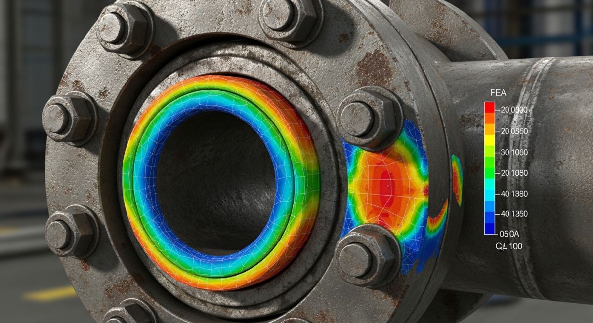
In my 20 years of troubleshooting piping systems, nothing stops a commissioning phase faster than a hissing flange. I have stood on offshore platforms where a single leaking hydrocarbon flange cost the operator hundreds of thousands of dollars per hour in deferred production. Bolted joints are often the weakest link in any high-pressure system. Understanding how to perform a rigorous flange leakage calculation is not just a theoretical exercise; it is a core safety requirement to prevent catastrophic releases, fires, and environmental hazards.
When we design piping networks, we spend a lot of time on pipe wall thickness and pipe support spans. However, the interfaces—the bolted flange connections—are where the real-world failures occur. External piping loads, such as thermal expansion, seismic movements, and weight, impose bending moments and axial forces directly onto these joints. If these forces are not accounted for, they will pry the flange faces apart, leading to immediate gasket bypass.
- Equivalent pressure methods provide a rapid, conservative first-pass check for external piping loads.
- ASME Section VIII Division 1 Appendix 2 remains the global standard for design-stage flange stress calculations.
- Rigorous finite element analysis is necessary for high-temperature, cyclic, or highly critical services.
Complete Course on
Piping Engineering
Check Now
Key Features
- 125+ Hours Content
- 500+ Recorded Lectures
- 20+ Years Exp.
- Lifetime Access
Coverage
- Codes & Standards
- Layouts & Design
- Material Eng.
- Stress Analysis
Why Flange Leakage Analysis Matters for Piping Integrity
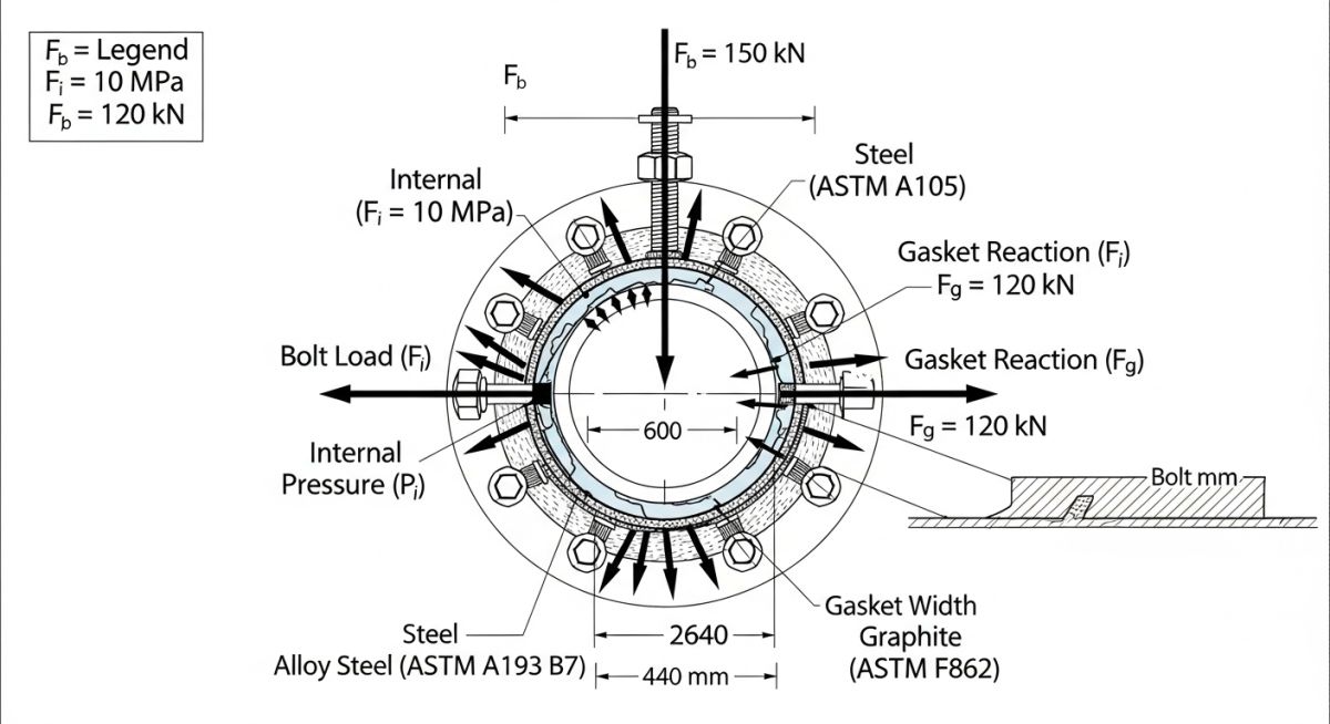
To perform a comprehensive flange leakage analysis, we must look at how external forces interact with internal pressure. When a piping system undergoes thermal expansion, it exerts a bending moment (M) and an axial force (F) on the flange joint. The bending moment tries to rotate one flange relative to the other, compressing the gasket on one side while unloading it on the opposite side. If the gasket stress on the unloaded side drops below the minimum threshold required to maintain a seal, a leak path opens.
In my practice, we primarily use three methods to evaluate this behavior: the Equivalent Pressure Method (also known as the Kellogg Method), the ASME Section VIII Division 1 Appendix 2 design method, and the ASME PCC-1 guidelines for bolted flange joint assembly.
The Equivalent Pressure Method (Kellogg Method)
The Kellogg Method is the most common first-pass analytical tool used by piping stress engineers. It converts external bending moments and axial forces into an “equivalent internal pressure” (P_eq). This equivalent pressure is then added to the actual operating pressure (P) to calculate a total effective pressure (P_total).
P_eq = P + (4 * F) / (pi * G^2) + (16 * M) / (pi * G^3)
Where:
– P_eq is the total equivalent design pressure (psi or MPa).
– P is the internal operating or design pressure (psi or MPa).
– F is the external axial force (lb or N), taken as positive for tension.
– M is the external bending moment (in-lb or N-mm).
– G is the gasket reaction diameter (inches or mm), which is the diameter of the gasket load reaction line.
– pi is the mathematical constant Pi (approximately 3.14159).
Once you calculate P_total, you compare it directly against the maximum allowable pressure rating of the flange at the design temperature, as specified in ASME B16.5 or ASME B16.47. If P_total is less than the rated pressure, the flange is deemed acceptable.
ASME Section VIII Division 1 Appendix 2 Method
For custom flanges or highly critical applications, we must perform a detailed stress analysis using the rules of ASME Section VIII Division 1 Appendix 2. This method calculates the required bolt loads for two distinct conditions:
1. Gasket Seating Condition (W_m2): The minimum bolt load required to deform the gasket into the flange face irregularities at atmospheric temperature and pressure.
W_m2 = pi * b * G * y
2. Operating Condition (W_m1): The bolt load required to resist the hydrostatic end force while maintaining sufficient residual stress on the gasket to prevent leakage under design pressure.
W_m1 = H + H_p = (pi * G^2 * P) / 4 + 2 * pi * b * m * P * G
Where b is the effective gasket width, m is the gasket factor (representing the ratio of residual gasket stress to internal pressure), and y is the gasket seating stress (psi or MPa).
The table below outlines the standard gasket factors (m) and seating stresses (y) defined in ASME Section VIII Division 1 Appendix 2. These values are fundamental for executing accurate flange leakage calculations.
| Gasket Material | Gasket Factor (m) | Seating Stress (y – psi) | Seating Stress (y – MPa) | Typical Applications |
|---|---|---|---|---|
| Spiral Wound (316SS/Graphite) | 3.00 | 10,000 | 68.9 | High-pressure steam, hydrocarbons |
| Ring Joint (Soft Iron) | 5.50 | 18,000 | 124.1 | Very high pressure, oil & gas upstream |
| PTFE (Teflon) | 2.00 | 1,600 | 11.0 | Corrosive chemicals, low temperature |
| Compressed Non-Asbestos (CNAF) | 2.50 | 4,500 | 31.0 | Utility lines, water, low-pressure air |
Selecting the correct methodology depends on the criticality of the system. This matrix maps the core technical entities, structural acronyms, and physical parameters to their respective code references.
| Analysis Method | Primary Code Reference | Input Parameters | Output/Verification Criteria | Best Suited For |
|---|---|---|---|---|
| Equivalent Pressure (Kellogg) | ASME B31.3 | P, F, M, Gasket OD/ID | P_total <= Flange Rating | Standard piping stress analysis runs |
| ASME Section VIII App 2 | ASME BPVC Sec VIII Div 1 | Flange geometry, Bolt area, m, y | Flange hub/ring stresses <= Allowable | Custom flanges, pressure vessel nozzles |
| ASME PCC-1 Appendix O | ASME PCC-1 | Target bolt stress, Gasket limits | Assembly bolt torque values | Critical field assembly, leak troubleshooting |
| Finite Element Analysis (FEA) | ASME BPVC Sec VIII Div 2 | 3D CAD, Thermal gradients, Elastic-plastic properties | Plastic collapse, local strain limits | High-temperature cyclic service, severe transients |
Advanced Methods for Flange Leakage Analysis and Verification
Even the most precise flange leakage calculation is useless if the field installation is flawed. In my experience, over 80% of flange leaks are caused by poor installation practices rather than design errors. To bridge the gap between engineering calculations and field execution, I always mandate a strict site verification checklist based on ASME PCC-1 guidelines.
-
Flange Alignment Check:
Verify that flange faces are parallel within 0.5 mm and bolt holes align within 1.5 mm without using external force. -
Surface Finish Inspection:
Inspect flange serrations for radial scratches. Spiral-wound gaskets require a surface finish between 125 and 250 micro-inches AARH. -
Gasket Verification:
Confirm that the gasket material, rating, and dimensions match the piping specification sheet exactly. Never reuse a gasket. -
Bolt Lubrication:
Apply a high-quality anti-seize lubricant (with a known friction coefficient, typically 0.11 to 0.15) to bolt threads and nut bearing faces. -
Torque Pattern Execution:
Utilize a multi-stage cross-pattern tightening sequence (30%, 60%, 100% torque) followed by a final circular pass to ensure uniform gasket compression.
Field Case Study: Real-World Application
During the commissioning of a refinery expansion project, a 24-inch Class 300 hydrocarbon line operating at 320 degrees Celsius experienced recurring leaks at a critical flanged joint during the thermal heat-up phase. The initial design team had verified the flange rating using standard pressure-temperature tables but had neglected the external piping loads. When the line reached operating temperature, thermal expansion of the piping loop generated an external bending moment of 45,000 N-m, which exceeded the gasket seating pressure and caused a hazardous leak.
I was brought in to resolve the issue. We performed a detailed flange leakage analysis using the Kellogg equivalent pressure method and verified the results with ASME Section VIII Appendix 2 calculations. The analysis revealed that the combined internal pressure and equivalent pressure from the thermal moment exceeded the Class 300 rating by 18%. To solve this, we modified the piping layout by installing a low-friction slide bearing to reduce the bending moment to 12,000 N-m. We also upgraded the gasket from a standard compressed fiber sheet to a spiral-wound gasket with an inner ring. The joint was reassembled using hydraulic torque wrenches to the calculated target torque. The system was restarted and has operated leak-free for over five years.
My direct recommendation for any high-temperature or high-pressure piping system is to mandate a formal flange leakage calculation during the stress analysis phase. Never assume that a standard flange rating is sufficient if the piping layout has short, stiff runs that generate high thermal moments.
Frequently Asked Engineering Questions
What is the difference between the Kellogg method and ASME Section VIII Appendix 2?
How does temperature affect flange leakage calculations?
Why is bolt torque control critical for preventing flange leakage?
Can we use the equivalent pressure method for high-pressure class flanges?
What role does gasket selection play in flange leakage analysis?
How does ASME PCC-1 guide the assembly of bolted flange joints?

📚 Recommended Resources: flange leakage analysis
Read these Guides
🎓 Advanced Training


Related posts:
![A mechanical sucker rod pumpjack operating in an oil field at sunset]()
What is Sucker Rod Pump System in Oil Production?
![Piping material engineer reviewing technical specifications on a tablet in an industrial plant.]()
How a Piping Material Engineer Drives Industrial Project Success
![Industrial refinery plant showing various types of static equipment]()
What is Static Equipment? Types and List of Static Equipments
![Side-by-side comparison of industrial process piping and power plant steam piping systems.]()
Differences Between ASME B31.3 and B31.1: B31.3 vs B31.1
![Large industrial steel storage tank under construction with cranes and scaffolding]()
Storage Tank Construction Method Statement: Step-by-Step Engineering Guide
![Cutaway diagram of a globe control valve highlighting the internal valve trim components]()
What is a Valve Trim? Types, Components, and Selection


