What is the Minimum Distance Between Welds in Piping?
In my 20+ years of managing piping fabrication yards and reviewing isometric drawings for heavy industrial projects, I have seen more spools rejected due to improper weld spacing than almost any other dimensional error. It is a classic conflict: the piping designer wants to fit a branch connection or a support as close to a girth weld as possible to save space, while the welding inspector knows that placing welds too close together is a recipe for structural failure.
When two welds are placed in close proximity, their thermal profiles interact. This interaction does not just double the heat input; it creates a highly localized, complex triaxial residual stress state that can severely compromise the ductility and toughness of the base metal. Understanding the engineering physics behind this phenomenon and knowing how to apply international code rules is a fundamental requirement for any piping or structural engineer.
Key Takeaways
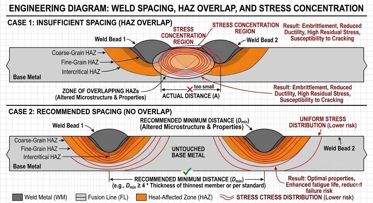
- HAZ Overlap: Placing welds too close together causes their Heat-Affected Zones to overlap, leading to localized grain growth, embrittlement, and microcracking.
- The 3t Rule: The industry standard rule of thumb for minimum spacing is three times the nominal wall thickness (3t) or 1.5 inches (38 mm), whichever is greater.
- Code Nuances: While some codes like ASME B31.3 do not mandate a single hard numerical limit for all services, they require the designer to account for stress concentrations and NDT limitations.
- NDT Access: Physical clearance is required not just for metallurgical reasons, but to allow proper access for volumetric examinations like Radiographic Testing (RT) and Ultrasonic Testing (UT).
Determining Minimum Distance Between Welds in Piping
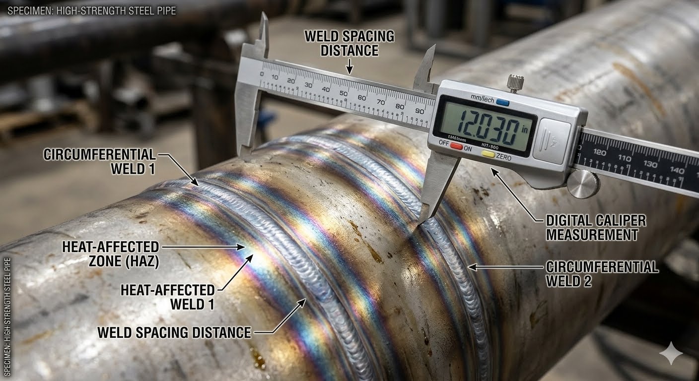
To understand why the minimum distance between welds is so heavily scrutinized, we must look at the metallurgy of a weldment. When we deposit weld metal, the intense heat of the arc melts the joint edges, but it also conducts rapidly into the surrounding base metal. This adjacent region, which does not melt but undergoes significant microstructural changes due to the thermal cycle, is the Heat-Affected Zone (HAZ).
In carbon and low-alloy steels, the HAZ experiences temperatures ranging from just below the melting point down to the lower transformation temperature (approximately 727 degrees Celsius). Within this zone, we observe grain coarsening, recrystallization, and phase transformations. If we place a second weld close enough that its HAZ overlaps the first, we subject this already altered microstructure to a second thermal cycle. This secondary thermal spike can cause extreme grain growth, reduce the fracture toughness of the material, and promote the formation of hard, brittle phases like martensite, which are highly susceptible to hydrogen-induced cracking.
The Physics of Residual Stress Accumulation
As a weld pool cools, the liquid metal solidifies and contracts. This thermal contraction is highly constrained by the surrounding cold base metal, which prevents the weld from shrinking freely. This constraint generates high tensile residual stresses within the weld metal and the adjacent HAZ, often reaching or exceeding the yield strength of the base material.
If two welds are positioned too close together, their individual tensile residual stress fields superimpose. Instead of two localized, independent stress peaks, we get a single, massive, continuous zone of high tensile stress. This triaxial stress state severely limits the material’s ability to deform plastically, drastically increasing the risk of brittle fracture under external mechanical loads, thermal expansion, or cyclic fatigue.
Mathematical Calculation of Minimum Spacing
While many codes provide empirical rules of thumb, we can analyze the minimum spacing mathematically based on the plate or pipe wall thickness. The standard industry formula used to establish the absolute minimum distance between weld toes is:
Where t is the nominal wall thickness of the thicker component. Let us look at a practical engineering calculation example:
Calculation Example: Heavy-Wall Steam Piping
Given Parameters:
- Pipe Material: ASTM A106 Grade B
- Nominal Pipe Size (NPS): 12-inch
- Schedule: Schedule 120
- Nominal Wall Thickness (t): 25.4 mm (1.00 inch)
Step 1: Calculate the thickness-based limit (3t)
3 * t = 3 * 25.4 mm = 76.2 mm (3.00 inches)
Step 2: Compare with the absolute minimum limit (38 mm / 1.5 inches)
76.2 mm > 38 mm
Conclusion:
The minimum distance between the toes of adjacent welds on this spool must be 76.2 mm (3.00 inches).
If we were dealing with a thin-walled pipe, say a 2-inch Schedule 40 pipe with a wall thickness of 3.91 mm, the calculation would yield:
3 * 3.91 mm = 11.73 mm.
Since 11.73 mm is less than the absolute minimum of 38 mm (1.5 inches), the 38 mm limit governs. This absolute minimum ensures that there is sufficient physical clearance for the welder’s torch, proper gas shielding, and visual inspection.
Code Rules for Minimum Distance Between Welds
Different international standards approach the minimum distance between welds with varying degrees of prescription. For instance, some codes provide hard numerical limits, while others focus on stress concentration factors and non-destructive testing (NDT) accessibility.
| Standard / Code | Minimum Distance Requirement | Technical Justification & Scope | Reference Section |
|---|---|---|---|
| ASME B31.3 (Process Piping) | No explicit numerical limit; recommends avoiding HAZ overlap and ensuring NDT clearance. Industry standard uses 3t or 38 mm. | Focuses on stress concentration and the ability to perform proper radiographic or ultrasonic examination of the joints. | ASME B31.3 Chapter V |
| ASME Section VIII Div 1 (Pressure Vessels) | Adjacent circumferential welds must be separated by at least 3t or 38 mm (whichever is greater) unless the joint is fully radiographed. | Prevents the accumulation of residual stresses in pressure-retaining shells and heads under high internal pressure. | ASME Sec VIII Div 1 UW-9 |
| AWS D1.1 (Structural Welding) | Minimum spacing between welds on a single member should be sufficient to prevent thermal interaction, typically 50 mm for dynamic loads. | Addresses fatigue life and cyclic loading in structural steel members, preventing premature crack initiation. | AWS D1.1 Section 5 |
| EN 13480 (Metallic Industrial Piping) | Minimum distance between adjacent butt welds must be at least 3 times the wall thickness or 50 mm, whichever is greater. | Strict European standard designed to guarantee high fracture toughness in industrial piping networks. | EN 13480-4 Clause 7.2 |
| BS 2633 (Class I Arc Welding) | Minimum distance of 4t or 100 mm is recommended for high-temperature, high-pressure steam applications. | Specifically tailored for power piping where creep and thermal fatigue are primary failure mechanisms. | BS 2633 Clause 11 |
To assist design engineers and quality control inspectors in mapping out their welding procedures, this matrix correlates key technical entities, physical parameters, and their corresponding standard references.
| Technical Entity | Acronym | Physical Parameter / Limit | Standard Reference |
|---|---|---|---|
| Heat-Affected Zone | HAZ | Width typically ranges from 2 mm to 10 mm depending on heat input. | AWS A3.0 |
| Post-Weld Heat Treatment | PWHT | Mandatory for carbon steels over 38 mm thickness to relieve residual stress. | ASME Sec VIII Div 1 UCS-56 |
| Non-Destructive Testing | NDT | Requires minimum 50 mm clearance for transducer placement in UT. | ASME Section V |
| Welding Procedure Specification | WPS | Defines maximum allowable heat input to control HAZ width. | ASME Section IX |
| Ultimate Tensile Strength | UTS | Must not degrade in the overlapped HAZ region. | ASTM A370 |
Field Checklist for Minimum Distance Between Welds
In my years on site, I have found that relying on the fabricator’s memory is a high-risk strategy. Having a structured, physical checklist that inspectors must sign off on before the arc is struck is the only way to guarantee that the minimum distance between welds is maintained.
Pre-Welding Fit-Up Verification Steps
-
Verify Nominal Wall Thickness (t): Identify the nominal wall thickness of both components from the piping isometric or drawing. Note the thicker component to calculate the 3t limit.
-
Calculate the Spacing Threshold: Multiply the nominal wall thickness by 3. Compare this value to 38 mm (1.5 inches). The governing minimum distance is the larger of the two values.
-
Measure Toe-to-Toe Distance: Use a certified bridge cam gauge or caliper to measure the physical distance between the proposed weld prep edge (or existing weld toe) and the adjacent weld toe. Do not measure from centerlines.
-
Check Branch Connection Proximity: Ensure that any weldolets, threadolets, or reinforcing pads are positioned so that their weld toes are at least 3t or 38 mm away from any circumferential girth welds.
-
Verify NDT Clearance: Confirm that the physical spacing allows sufficient clearance for the planned non-destructive testing. For example, ensure there is enough flat pipe surface for an ultrasonic shear-wave transducer to scan the full volume of the weld.
-
Document and Sign-Off: Record the actual measured distance on the fit-up inspection report. Do not release the joint for welding until the inspector has signed off on the spacing.
Field Case Study: Real-World Application
Upon field inspection, I discovered that a 2-inch weldolet bypass connection had been welded directly adjacent to a circumferential girth weld. The distance between the toe of the weldolet weld and the toe of the girth weld was only 15 mm—far below the calculated 3t limit of 76.2 mm. The overlapping thermal cycles had created a localized zone of extreme hardness (340 HBW) and high residual tensile stress, which cracked under the thermal expansion cycles of the steam line.
To rectify the failure, we cut out the entire damaged section of the spool. I redesigned the layout to move the weldolet bypass 150 mm away from the girth weld, well exceeding the 3t limit.
The new joint was welded using a strictly controlled preheat of 200 degrees Celsius, followed by a full Post-Weld Heat Treatment (PWHT) at 705 degrees Celsius to temper the HAZ and relieve residual stresses. Hardness testing after PWHT showed a safe maximum of 210 HBW. The line has now been in continuous operation for over five years with zero issues.
This case highlights why we cannot afford to treat weld spacing as a minor drafting detail. It is a critical mechanical design parameter. When space is tight, it is always better to negotiate a piping reroute or use a specialized fitting (like a tee) rather than compromise on the minimum distance between welds.
Frequently Asked Engineering Questions
Why is the minimum distance between welds so critical in high-pressure piping?
Does ASME B31.3 specify an exact numerical minimum distance between welds?
How does wall thickness affect the minimum distance between welds?
Can post-weld heat treatment (PWHT) compensate for insufficient weld spacing?
What is the difference between toe-to-toe and centerline-to-centerline weld spacing?
How do you handle weld spacing for small-bore piping (under 2 inches)?
===FAQ_BLOCK===

Complete Course on
Piping Engineering
Check Now
Key Features
- 125+ Hours Content
- 500+ Recorded Lectures
- 20+ Years Exp.
- Lifetime Access
Coverage
- Codes & Standards
- Layouts & Design
- Material Eng.
- Stress Analysis