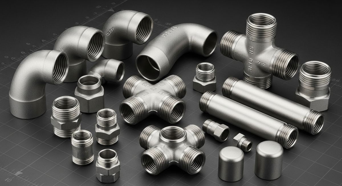
What are Tube Fittings and How Do They Work?
In my 20 years of commissioning refinery piping systems, I have seen my share of spectacular failures. I still remember a cold morning in a hydrogen pilot plant when a poorly installed compression fitting blew clean off its tubing run at 350 bar. The culprit? A technician had mixed up a standard pipe thread with a tube fitting connection, assuming they were interchangeable. They are not.
Understanding the mechanics of tube fittings is not just about making a tight connection; it is about safety, system integrity, and long-term reliability. Tubing systems require a level of precision that standard piping simply cannot match. In this guide, I will break down the engineering principles behind these components, their distinct types, and how they differ fundamentally from pipe fittings.
Key Engineering Takeaways
- Double-ferrule compression fittings provide the most reliable mechanical grip and seal for high-pressure applications.
- Tubing is measured by its exact outside diameter (OD), whereas piping is designated by nominal pipe size (NPS).
- Material compatibility between the tubing and the fitting is mandatory to prevent galvanic corrosion and ensure a proper swaging action.
The primary reason we turn to tubing and tube fittings is the wall thickness of the conduit. Standard pipes have thick walls designed to be threaded or welded. Tubing, on the other hand, features thinner walls with highly controlled outside diameters. Because you cannot safely cut threads into thin-walled tubing without compromising its structural integrity, we rely on mechanical fittings to do the heavy lifting.
The Mechanics of the Double-Ferrule Design
The double-ferrule compression fitting is the gold standard in industrial instrumentation. When you tighten the fitting nut, it drives the back ferrule forward, which in turn pushes the front ferrule into the fitting body’s angled seat.
- The Front Ferrule: Creates the primary seal against the fitting body and the tubing outside diameter.
- The Back Ferrule: Mechanically grips the tubing, preventing it from backing out under high pressure. It also dampens system vibration, protecting the primary seal.
Calculating Allowable Working Pressure
To determine if a tubing system can safely handle your process pressures, we use Barlow’s Formula. This calculation is fundamental when designing systems under ASME B31.3:
Where:
P = Allowable working pressure (psi)
S = Maximum allowable stress of the material (psi) at design temperature (from ASME B31.3 Table A-1)
t = Nominal wall thickness of the tubing (inches)
D = Nominal outside diameter of the tubing (inches)
Never mix ferrules or fitting bodies from different manufacturers (e.g., Swagelok, Parker, Gyrolok). While they may look identical to the naked eye, their thread pitches, ferrule angles, and tolerances differ. Intermixing components compromises the swaging action and can lead to catastrophic high-pressure blowouts.
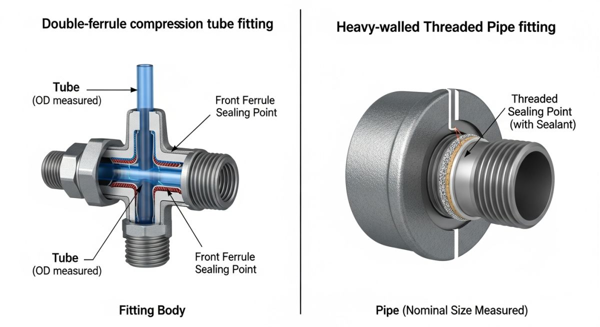
Key Differences: Tube Fittings vs. Pipe Fittings
The table below highlights the fundamental differences that every piping designer must keep in mind when selecting components for a fluid system.
The following data represents the allowable working pressures (psi) for fully annealed 316/316L stainless steel tubing conforming to ASTM A269 or equivalent standards. These values are calculated with a 4:1 safety factor.
| Tube OD (Inches) | Wall Thickness: 0.035″ | Wall Thickness: 0.049″ | Wall Thickness: 0.065″ | Wall Thickness: 0.083″ |
|---|---|---|---|---|
| 1/4″ | 5,100 psi | 7,500 psi | 10,200 psi | N/A |
| 3/8″ | 3,300 psi | 4,800 psi | 6,500 psi | N/A |
| 1/2″ | 2,600 psi | 3,700 psi | 5,100 psi | 6,700 psi |
| 3/4″ | N/A | 2,400 psi | 3,300 psi | 4,200 psi |
This matrix maps common tube fitting configurations to their primary design standards, typical applications, and material specifications.
| Fitting Type | Primary Standard | Typical Application | Key Material Grade |
|---|---|---|---|
| Double-Ferrule Compression | ASME B31.3 | Process Instrumentation Lines | 316 Stainless Steel / Alloy 400 |
| Single-Ferrule Compression | DIN 2353 / ISO 8434-1 | Medium-Pressure Hydraulics | Carbon Steel (Zinc Plated) |
| Cone and Thread (Medium/High) | ASME B31.3 Chapter IX | Ultra-High Pressure (Up to 60k psi) | Cold-Worked 316 SS |
| Flared Fittings (37-degree JIC) | SAE J514 / ISO 8434-2 | Mobile Hydraulic Equipment | Brass / Carbon Steel |
Selecting the wrong fitting can lead to system leaks, premature wear, or catastrophic failure. Over my career, I have developed a rigorous verification process that must be completed before any tubing system is released for construction.
Site Verification & Selection Checklist
-
Material Compatibility: Ensure the fitting material matches the tubing material (e.g., stainless steel fittings on stainless steel tubing). This prevents galvanic corrosion and ensures the fitting is harder than the tube for a proper grip.
-
Hardness Differential: Verify that the tubing is fully annealed and has a hardness lower than the fitting ferrules (typically HRB 80 or less for stainless steel). If the tubing is too hard, the ferrules cannot bite into it.
-
Temperature Derating: Apply temperature reduction factors to the allowable working pressure if the system operates above 100°F (37°C). For example, 316 SS requires a derating factor of 0.80 at 600°F.
-
Wall Thickness Limits: Check that the tubing wall thickness falls within the manufacturer’s recommended range. Tubing that is too thin may collapse under ferrule pressure, while tubing that is too thick will not deform properly.
-
Installation Gap Inspection: Use a physical gap inspection gauge during installation to verify that the fitting has been pulled up the required 1-1/4 turns (for sizes greater than 1/16″).
Field Case Study: Real-World Application
The Problem: Micro-Leaks in a Hydrogen Pilot Plant
During the commissioning of a high-pressure hydrogen pilot plant operating at 400 bar (5,800 psi), the system failed its initial helium leak test. Multiple micro-leaks were detected around the instrumentation panels. Upon close inspection, we discovered that the field technicians had intermixed double-ferrule fittings from two different major manufacturers. Additionally, they had used hard-drawn stainless steel tubing instead of fully annealed tubing, which prevented the back ferrule from biting into the tube wall.
The Outcome: Standardization and Remediation
I ordered an immediate halt to commissioning. We purged the entire inventory of mixed fittings and standardized on a single manufacturer’s double-ferrule design. We replaced the hard-drawn tubing with fully annealed ASTM A269 316L tubing (hardness < 80 HRB). After retraining the crew on proper pull-up procedures and using a gap inspection gauge on every joint, the system passed the helium leak test with zero leakage.
My Recommendation: Always establish a strict material control program on-site. Color-code or segregate fittings from different manufacturers to prevent accidental mixing, and verify tubing hardness certificates before installation begins.
Frequently Asked Engineering Questions
What is the difference between single-ferrule and double-ferrule fittings?
Can you reuse a compression tube fitting?
Why is tubing hardness so critical for fitting performance?
What is the difference between NPT and tube fitting threads?
How do you verify that a tube fitting is properly tightened?
Which standards govern the design and testing of tube fittings?
===FAQ_BLOCK===
Complete Course on
Piping Engineering
Check Now
Key Features
- 125+ Hours Content
- 500+ Recorded Lectures
- 20+ Years Exp.
- Lifetime Access
Coverage
- Codes & Standards
- Layouts & Design
- Material Eng.
- Stress Analysis