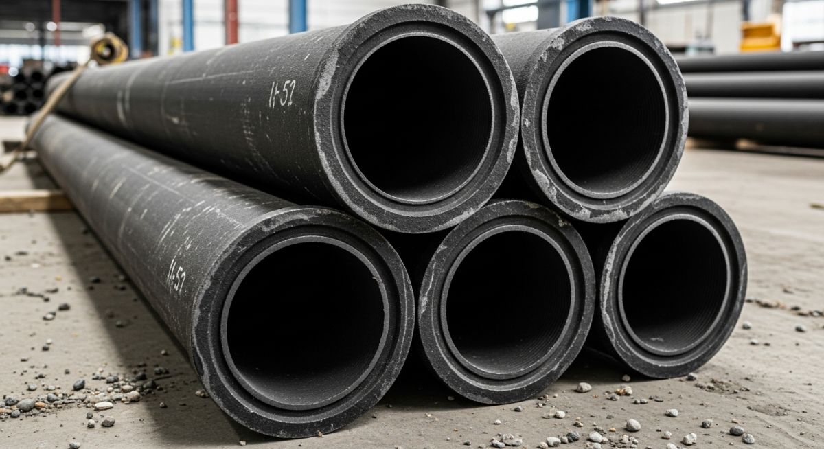
Cast Iron Pipes: Engineering Guide to Types, Joining, and Standards
In my 20-plus years of managing industrial piping installations, I have watched materials come and go, yet cast iron remains an absolute titan in municipal and structural drainage. When you are dealing with high-rise commercial buildings or deep underground municipal mains, the structural integrity and acoustic dampening of your piping system cannot be compromised. Plastic alternatives often fail under heavy earth loads or transmit excessive noise throughout a structure. That is where cast iron proves its worth.
This guide draws directly from my field experience and structural design records. We will break down the metallurgy, structural calculations, joint configurations, and installation standards that define successful cast iron piping systems. Whether you are designing a gravity-flow sanitary system or a high-pressure water distribution network, understanding these parameters is the difference between a system that lasts a century and one that fails within a decade.
Key Engineering Takeaways
- Understand the metallurgical differences between grey cast iron and ductile iron to select the correct pipe for pressure versus non-pressure applications.
- Master the structural load calculations using Marston’s formula to prevent trench crushing failures.
- Identify the correct joining methods, including hubless couplings and hub-and-spigot compression joints, for specific structural demands.
- Ensure strict compliance with ASTM A74, ASTM A888, and CISPI 301 standards during design and field inspection.
Why Cast Iron Pipes Remain the Industry Standard
To understand why we specify cast iron, we must look at its metallurgy. Grey cast iron contains carbon in the form of graphite flakes. These flakes interrupt the iron matrix, providing exceptional dampening capacity—which is why cast iron is incredibly quiet when wastewater rushes through it. However, these same flakes act as internal stress risers, making grey cast iron brittle under high tensile stress.
For pressure applications, we transition to ductile iron (often governed by AWWA C151). Ductile iron incorporates magnesium, which forces the graphite to form spherical nodules rather than flakes. This simple metallurgical shift dramatically increases tensile strength and ductility, allowing the pipe to bend under stress rather than crack.
Structural Load Calculations
When burying cast iron pipes, we must calculate the external earth load to determine the required pipe class. We utilize Marston’s Formula for loads on buried conduits in trenches:
Where:
- W_c = Vertical load on the pipe in pounds per linear foot (lb/ft).
- C_d = Trench load coefficient, which depends on the ratio of trench depth to width and the soil type.
- w = Unit weight of the backfill soil (typically 120 lb/ft³ for damp clay).
- B_d = Width of the trench at the top of the pipe in feet.
For internal pressure design in ductile iron pressure pipes, we adapt Barlow’s Formula to calculate the nominal wall thickness required to contain internal hydrostatic pressure:
Where:
- t = Net wall thickness in inches.
- P = Design internal pressure (including water hammer surge) in psi.
- D = Outside diameter of the pipe in inches.
- S = Allowable tensile strength of the material (typically 50 percent of the minimum yield strength, which is 42,000 psi for ductile iron, yielding S = 21,000 psi).
Joining Methodologies in the Field
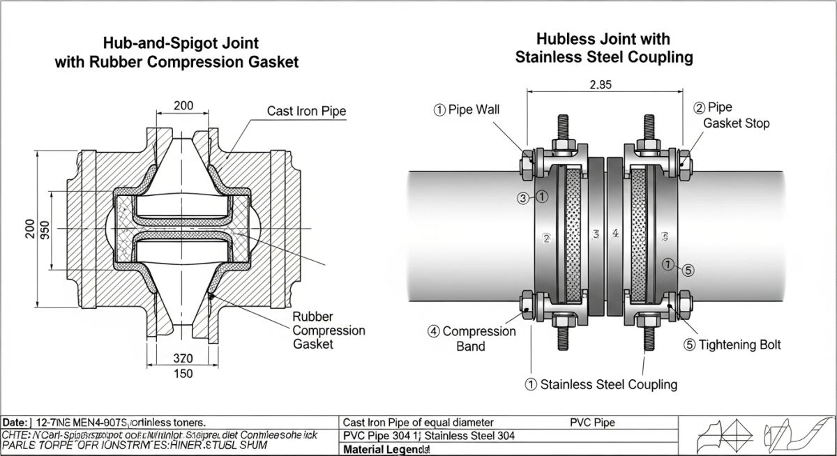
The selection of the joining method directly impacts both installation speed and structural flexibility. In modern installations, we primarily use two methods:
- Hubless (No-Hub) Joints: These pipes are manufactured without a bell end. They are joined using elastomeric sealing sleeves wrapped in a stainless steel shield with worm-gear clamps, conforming to ASTM C1277 or CISPI 310. This system is highly efficient for compact commercial plumbing shafts.
- Hub and Spigot (Bell and Spigot) Joints: The spigot end of one pipe is inserted into the hub end of the next. Historically, these were sealed with lead and oakum. Today, we utilize compression gaskets conforming to ASTM C564. This provides excellent structural deflection capabilities, making it ideal for underground installations subject to soil settlement.
The following tables provide the exact dimensional and pressure rating standards used during the design phase. These values are compiled from ASTM A74 (for soil pipes) and AWWA C151 (for ductile iron pressure pipes).
| Nominal Size (Inches) | Pipe Class / Type | Outside Diameter (Inches) | Wall Thickness (Inches) | Max Working Pressure (PSI) |
|---|---|---|---|---|
| 2 | ASTM A74 Service (SV) | 2.30 | 0.17 | Gravity Only |
| 4 | ASTM A74 Extra Heavy (XH) | 4.50 | 0.25 | Gravity Only |
| 6 | AWWA C151 Ductile Iron Class 52 | 6.90 | 0.31 | 350 |
| 12 | AWWA C151 Ductile Iron Class 52 | 13.20 | 0.37 | 350 |
| Standard Code | Application Scope | Material Grade | Key Joint Specification |
|---|---|---|---|
| ASTM A74 | Gravity Sanitary & Storm Drainage | Grey Cast Iron (Class 20) | Hub & Spigot (ASTM C564 Gaskets) |
| ASTM A888 | Hubless Sanitary Waste & Vent | Grey Cast Iron (Class 20) | Hubless Couplings (CISPI 310) |
| AWWA C151 | Water Mains & Pressure Sewers | Ductile Iron (60-42-10 Grade) | Push-on / Mechanical Joint (AWWA C111) |
How to Inspect Cast Iron Pipes on Site
In my years supervising field crews, I have learned that a cast iron installation is only as good as its bedding and joint torque. If the trench bottom is uneven, the rigid pipe will bridge the gaps, creating massive bending stresses that lead to shear failures once backfilled. The following checklist must be executed by the quality control inspector before any trench is closed.
Pre-Backfill Inspection Checklist
-
Trench Bedding Verification: Ensure a minimum of 4 inches of compacted sand or fine gravel bedding is placed. No large rocks or debris must contact the pipe wall. -
Torque Specification Check: Verify that all hubless coupling bands are torqued to exactly 60 inch-pounds (or 80 inch-pounds for heavy-duty couplings) using a calibrated t-handle torque wrench. -
Alignment and Slope: Confirm gravity lines maintain a minimum slope of 1/4 inch per foot for pipes under 3 inches, and 1/8 inch per foot for larger diameters. -
Hydrostatic Testing: Perform a 10-foot water column test (4.3 psi) for at least 15 minutes. Inspect every joint visually for weeping or moisture. -
Deflection Limits: For push-on joints, verify that the joint deflection does not exceed the manufacturer’s limit (typically 3 to 5 degrees depending on diameter).
Resolving Structural Failures in Cast Iron Pipes
The Problem: Shear Failure in a 10-Inch Gravity Sewer
During a municipal expansion project, a newly installed 10-inch grey cast iron gravity sewer line failed hydrostatic testing. CCTV inspection revealed a clean circumferential shear crack approximately 45 feet from the manhole. The contractor blamed a defective pipe casting.
Upon excavation, I discovered that the pipe had been laid directly on native rocky soil without the specified sand bedding. A large limestone boulder was resting directly beneath the failed joint. When the trench was backfilled and compacted with heavy machinery, the boulder acted as a fulcrum, concentrating the entire vertical load onto a single point, causing a classic bending shear failure.
The Outcome: Remediation and Structural Correction
We rejected the contractor’s claim of material defect. The failed section was cut out, and the trench was excavated an additional 6 inches below the pipe grade. We backfilled this zone with crushed stone bedding conforming to ASTM D2321.
The replacement pipe section was joined using heavy-duty stainless steel shielded couplings. The line successfully passed a subsequent 10-foot head water test with zero leakage. This failure could have been avoided entirely if the field inspector had verified the bedding before allowing backfill operations to commence.
My direct recommendation for any underground cast iron installation is to mandate continuous third-party inspection during the bedding and initial backfill phases. The cost of an inspector on-site is a fraction of the cost of excavating a failed line under a paved roadway.
Frequently Asked Engineering Questions
What is the difference between Service (SV) and Extra Heavy (XH) cast iron pipes?
Can cast iron pipes be used for chemical waste drainage?
Why is cast iron preferred over PVC for acoustic control in buildings?
How do you prevent internal corrosion in cast iron water mains?
What is the purpose of the stainless steel shield on hubless couplings?
How long can a properly installed cast iron pipe system last?
===
Complete Course on
Piping Engineering
Check Now
Key Features
- 125+ Hours Content
- 500+ Recorded Lectures
- 20+ Years Exp.
- Lifetime Access
Coverage
- Codes & Standards
- Layouts & Design
- Material Eng.
- Stress Analysis